Very Confused Then...
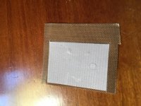
When I used just the grey layer (the lighter layer in my photo), had all kinds of problems - distortion, volume drop, etc.. When I replaced with both layers, everything cleared up! In the build video on diyAudio, the TekThings guy uses both layers as you can see in my photo here. The woven brown layer is pre-cut underneath the grey layer. What's going on?!
????
keratherm is just grayish* thing
if anything else is there , that's protective layer
power it off immediately and check what you did , if you already didn't cook poor mosfets
*I have pinky ones
When I used just the grey layer (the lighter layer in my photo), had all kinds of problems - distortion, volume drop, etc.. When I replaced with both layers, everything cleared up! In the build video on diyAudio, the TekThings guy uses both layers as you can see in my photo here. The woven brown layer is pre-cut underneath the grey layer. What's going on?!
Attachments
ya ever read Tom Sawyer ?
internet is same thing as Tom's plank fence , everyone can write any rubbish on it .....

OK, I can appreciate that, but does anyone have any idea why the amps were NOT operating properly until I went with both layers on the Keratherm?
When I used just the grey layer (the lighter layer in my photo), had all kinds of problems - distortion, volume drop, etc.. When I replaced with both layers, everything cleared up! In the build video on diyAudio, the TekThings guy uses both layers as you can see in my photo here. The woven brown layer is pre-cut underneath the grey layer. What's going on?!
Jeez....you guys are confusing me...I believe its ONLY the grey pad that's keratherm and that needs to be placed between the chip and heatsink....without any thermal paste....
Sent from my iPhone using Tapatalk Pro
Yes - Only The Grey
Sorry for my contribution to the confusion... All evidence points to the grey only in spite of what I experienced. The video on diyAudio appears to be incorrect. The guy never says "apply both layers," but he clearly does so in the build.
In the meantime, I have one amp working beautifully with just the grey layer. The other not... but when I add the backing, viola, all good.
Scratching my head in confusion. Bad mosfet maybe?
Jeez....you guys are confusing me...I believe its ONLY the grey pad that's keratherm and that needs to be placed between the chip and heatsink....without any thermal paste....
Sent from my iPhone using Tapatalk Pro
Sorry for my contribution to the confusion... All evidence points to the grey only in spite of what I experienced. The video on diyAudio appears to be incorrect. The guy never says "apply both layers," but he clearly does so in the build.
In the meantime, I have one amp working beautifully with just the grey layer. The other not... but when I add the backing, viola, all good.
Scratching my head in confusion. Bad mosfet maybe?
Another Clue...
Thank you guys for indulging me in my quest to figure out why the second amp is just not working.
This just in: I realize now that the bad amp is generating no discernable heat. The good one is warming up nicely, heatsinks mildly warm to the touch from the mosfets.
Note: I have run both amps only at low volume thus far. I am getting signal through the bad one, but highly distorted and way down in amplitude.
The grey Insulators ones are official also. They were never very pink...in fact maybe we just wanted them to be pink! ")
That video is wrong - he cuts out the clear backing sheet backing sheet and uses it, - Wrong- Dont use the clear backing sheet!
The most logical reason the amp worked with the clear backing sheet is as has been mentioned- without the backing sheet there was a short through the rubbery correct insulator.. maybe a sharp piece of metal or wire stuck in the Keratherm or a metal burr on the heatsink poking through the Keratherm. Its quite soft which is why it works- it conforms to the surfaces..
OK - to check for a short, I connect the voltmeter to the chassis and any pin on the mosfet? Middle pin?
Are there other ways the mosfet could be shorting? I've gone through every solder point and all looks good on the board.
What if I double up on the Keratherm? Still enough heat transfer?
Are there other ways the mosfet could be shorting? I've gone through every solder point and all looks good on the board.
What if I double up on the Keratherm? Still enough heat transfer?
If you could post pictures of working and non working amps it could be helpful for people to assist you in trouble shooting.
It might be worth checking that there are no excessive legs touching the heatsink for the non working amp components
Sent from my F8332 using Tapatalk
It might be worth checking that there are no excessive legs touching the heatsink for the non working amp components
Sent from my F8332 using Tapatalk
Has anyone looked into using the positive feedback method used in IHQuam's take on the F7? If indra1's post 579 (F7 thread) on applying it to the F5 could be used on the ACA, just two resistors could give us all those positive benefits. My WAG would be to cut the trace between R14 and -OUT, insert Rsen between R14 and -OUT. Then run Rfbp between -OUT and the Gate of Q4.
I'm just getting ready to start my first build and it would be fun to include the positive feedback; R ratings on the resistor values would be appreciated.
(http://www.diyaudio.com/forums/pass-labs/275921-first-watt-f7-review-58.html#post4620544)
I'm just getting ready to start my first build and it would be fun to include the positive feedback; R ratings on the resistor values would be appreciated.
(http://www.diyaudio.com/forums/pass-labs/275921-first-watt-f7-review-58.html#post4620544)
Any positive benefit to ACA from positive feedback?
From the FirstWatt F7 review thread:
(I will build one with PF and one without and do the comparison myself, when I get the topology and values required. This novice needs some guidance.
Thanks
From the FirstWatt F7 review thread:
...and...Positive current feedback is very simple, works well when applied in very moderate doses, and provide all manner of new entertainment.
<snip> The best part is that you can even do this with amps you have already built, and impress your audio buddies with the awesome and mysterious power of positive feedback!
Mr. Pass, Do you think the addition of positive feedback to the Amp Camp Amp could decrease the output impedance and increase the damping factor enough to be audible?The best in this regard is the one with the highest amount of negative feedback and/or the topology with the lowest intrinsic (open loop) output impedance.
Of course if you already have a very low output impedance, the need for
positive current feedback is very small.
(I will build one with PF and one without and do the comparison myself, when I get the topology and values required. This novice needs some guidance.
Thanks
I think it's even easier, Rsen=R14, just probably needs to be tweaked a bit, and run the resistor between -OUT and Q4's Gate.My WAG would be to cut the trace between R14 and -OUT, insert Rsen between R14 and -OUT. Then run Rfbp between -OUT and the Gate of Q4.
Does somebody have a LTSpice model they'd be willing to share, or the ZTX450 and IRFP240 models? PM me and I'll send you my email address. Thanks in advance.
Unstable voltage at test point
Over the last two weeks I've been trying to bring up my ACA. Two amps on one very large heatsink. My power supply is a 24V Meanwell rated at 14.5 amps in a separate chassis. The boards are fist generation, and I haven't done the 2.2k resistor mod. I may go to a 28V linear thinking that the added 4 volts might cause issues with the 2.2k mod.
One channel came up perfectly, and I have listened to it for about 6 hours. Very encouraging. The other channel shows erratic voltages at the Q1 drain (2-3 volts variation), initially around 15V or so and on powerup then dropping over 30-40 minutes to about 7.5V. It varies by the second within 2-3 volts around the 'center' voltage. Turning the pot seems to have no affect.
It shows no sign of distress, nothing has been any warmer than the working channel. I took it off the sink yesterday and reflowed every solder joint, but no change today when reassembled and powered up.
I have parts to replace all the semis and the pot, as well as most of the rest.
Do these symptoms suggest failure in a specific place?
All suggestions most welcome. TIA
Skip
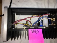
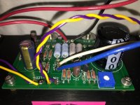
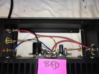
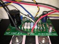
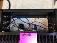
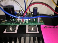
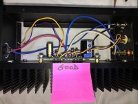
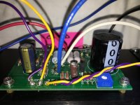
The Good, The Bad, The Ugly
DIY friends. Finally had an opportunity to take and post some photos of my wayward 1st attempts at building amps.
So, first, 4 photos of the good one.
Then, 4 photos of the bad one.
The ugly? Well, one look at my soldering...
Thanks for any and all sleuthing to help this rookie DIYer...
I must confess, about ready to throw in the towel
Attachments
- Home
- Amplifiers
- Pass Labs
- Amp Camp Amp - ACA