HF performance will suffer
btw. input resistor (R11) is directly in correlation with other feedback net resistor (R12) thus defining both input impedance and gain
Thanks for the quick reply. That is what I was afraid of.
It was suggested elsewhere that I add a B1 buffer after the preamp. It doesn't look like that would be too expensive of a solution.
Is there an easy way to raise the input impedance without messing up anything else on the amp? Just raising R11 seems too...
Just curious, what's the output impedance of the tube preamp?
Just curious, what's the output impedance of the tube preamp?
It is showing a maximum of 68k

Hi guys
Have a question around setting bias of this amp. Does it make any difference if we attach a load to the output? Someone told me I needed to but never read it here anywhere.....
4 Channels on my 420mm x 275mm heatsink runs way too hot, can't touch it!!! Just wanted to make sure my bias setting method was correct, no load and 10v on the Q1 drain.
Is it correct that these run at about 26 watts load or no load? So that means my setup would be around 100 watts at idle, hot.....
Thanks
Attachments
all help you need is here: http://www.firstwatt.com/pdf/art_amp_camp_1.pdf
Hi Zen Mod
I bought the amp second hand so didn't build it.Therefore I'm not sure how to set the inner side of the output cap
Any help will be greatly appreciated.
Thanks
Chris
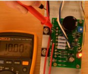
Chris,
You need the pictorial build guide. Here's a screen shot of the adjustment. Multimeter to Q1 and ground. Set the pot (blue plastic square with white screw adjustment) to 15v (or whatever your target is). Keep cover on as it will be when finished. With amp on, wait half hour and adjust again.
Attachments
How to replace of 2SK170 by J111
I have exhausted my 2SK170's I got from US and am actively looking for replacement JFET's. J111 as per these comments looks like a great candidate, got them super cheap from RSDelivers.in however it doesn't look like it's an apple to apple replacement for 2SK (.. tried replacing them in my working ACA channel..including considering the leads are different for J111), but did not work...guys, need some direction/headstart to make this possible.
Nelson Pass mentioned Fairchild J111 being a possible substitute for 2sk170 for F5. Only $0.16 each, 73,000 parts in stock at Mouser. It seems like it would work very well in the ACA
I have exhausted my 2SK170's I got from US and am actively looking for replacement JFET's. J111 as per these comments looks like a great candidate, got them super cheap from RSDelivers.in however it doesn't look like it's an apple to apple replacement for 2SK (.. tried replacing them in my working ACA channel..including considering the leads are different for J111), but did not work...guys, need some direction/headstart to make this possible.
J309
when you have it , buzz and I'll tell which resistor to change
Thanks ZM
J309's are available and not too costly, there are 3 options ON Semi/NXP/Fairchild .... all smd [emoji31]
- Home
- Amplifiers
- Pass Labs
- Amp Camp Amp - ACA