That is very cool, laverda!!
I'm new to this concept (using copper strips) so perhaps you can explain it to me:
Q1: I assume the copper strips are connecting a bank of caps? 12 caps in each bank?
Yes...
Q2: How did you decide the copper thickness?
3mm thick is more than adequate (which is what I used) This was a design criteria, only the two caps each end of each bank have fixing clamps. The caps in the middle are held in place by just the copper.
Q3: How do you stop the copper tarnishing? Spray with a clear coat?
I don't care if it tarnishes, it has not been sprayed with anything, its just newish.
Q4: The caps have screw connectors? What make caps are these and where do you buy them from?
They are Felsic caps purchased from a distributor here in the UK (my biggest single expense)
Q5: What gauge wire do you use to connect the copper strips to where the DC rails connect to?
Equipment wire 32/02, nothing special. That's for 32v rails.
Q6: Is that a complete amp ... or just the PSU?
MMmmm Complete...2 channel amp...
Q7: If it's the complete (stereo - which you are going to split into monos) amp ... where are the heatsinks for the MOSFETs?
See photos....
Thanks,
Andy
Andy, maybe do some more homework.
Andy, maybe do some more homework.
Ummm ... I'm doing my homework (before I build).
")
But thank you for answering my Qs before your snide remark.
Andy
More homework!
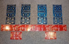
Can someone please confirm that I have my thoughts right about the attached pic. I want to build the F5-T v2:
1. For an F5-T v2, there are 2x O/P PCBs per channel. One PCB is for 2x N-channel MOSFETs ... the other is for 2x P-channel MOSFETs?
2. Each O/P PCB has its own PS PCB?
3. Also there is a Gain Stage PCB (for each channel) which feeds both O/P PCBs?
Thanks,
Andy
Attachments
Ummm ... I'm doing my homework (before I build).
But thank you for answering my Qs before your snide remark.
Andy
I apologise Andy, it was not so much snide remark but maybe I'm questioning 'your questions' as they should be obvious if your going to undertake the build.
I have photos which should/will help,
An externally hosted image should be here but it was not working when we last tested it.
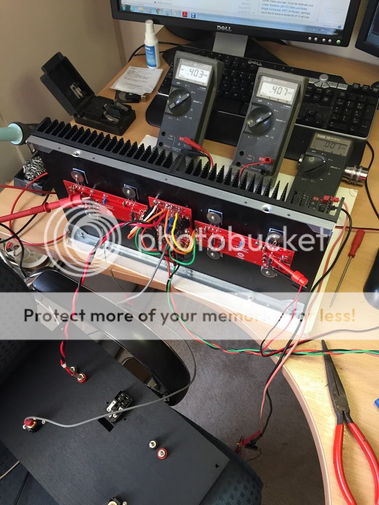
One channel completed Front End (FE) board (gain stage) centre and one P and N either side all tree boards are on one 5u 400mm deep sink. I have 'one' + 32 - 32 and a 0volts supply per channel. (each FE board) which in turn piggy backs to the O/P boards. In this photo I'm supplying this off my bench PSU set at + & -32v. The bias is set .4v which was raised over some hours from an initial setting of .2v, monitoring heat sink temperature every now and then. The offset is quite stable and easily set within 1.0mv. However this is not the way to do it...(on the bench) you need to assemble the whole amp (lid on) switch on let it warm up and then adjust.
An externally hosted image should be here but it was not working when we last tested it.
This photo shows the layout...it is a tight fit really and air flow was an issue, all those caps get in the way of the air flow through the chassis grid..but I've resolved that now. I used foot extensions to lift the chassis 25mm off the floor so a clear air flow path could be had to the underside of the chassis.
Last edited:
More homework!
Can someone please confirm that I have my thoughts right about the attached pic. I want to build the F5-T v2:
1. For an F5-T v2, there are 2x O/P PCBs per channel. One PCB is for 2x N-channel MOSFETs ... the other is for 2x P-channel MOSFETs?
2. Each O/P PCB has its own PS PCB?
No..each FE board (gain stage) has its own PSU supply which in turn piggy backs to both P & N O/P boards.
3. Also there is a Gain Stage PCB (for each channel) which feeds both O/P PCBs?
Yes
Thanks,
Andy


andyr -
Are you building monoblocks or stereo? How many transformers do you have?
This thread shows a v2 being built - http://www.diyaudio.com/forums/pass-labs/254056-f5turbo-illustrated-build-guide.html
PSU guide -
http://www.diyaudio.com/forums/powe...circuit-board-v3-illustrated-build-guide.html
Are you building monoblocks or stereo? How many transformers do you have?
This thread shows a v2 being built - http://www.diyaudio.com/forums/pass-labs/254056-f5turbo-illustrated-build-guide.html
PSU guide -
http://www.diyaudio.com/forums/powe...circuit-board-v3-illustrated-build-guide.html
Just to see I tweaked the bias to .5v and pulling 2.3 amps per side (the sink could not hold it) The point being NP states the optimum for the F5t is .4v bias. LOL why did I even bother...For me the lesson was 'do as your told boy...'[/QUOTE]
I see that you have the diodes in your build. NP's exact words are "Then adjust the bias to a point below where the idle current starts to really take off. You should find that this point is around 0.4volts across the 1ohm resistors."
Most of us here have kept the bias below 0.4V just to ensure that the bias does not runaway when incorporating diodes in their build.
nash
Nash, what should I/we be looking to set bias.. .375v ? I've been running at .4 for some weeks but the summer is coming.....��
TIA
Graham
Not sure from your pics whether you have, but I think you will find out only after you have boxed everything up and closed the lid. You will find that the bias rises quite a bit with the lid on, so you will have to start low.
6L6 has proposed an easy rule- increase bias untill in hot ambient temperatures the heatsink does not exceed 50-55C or the Mosfets do not exceed 65C whichever occurs first.
To give you an approximation, in my F5TV3 monos with 46V rails I run at 0.32V across the source resistors and the max heatsink temp on a really hot 28C day is under 52C.
nash
andyr -
Are you building monoblocks or stereo? How many transformers do you have?
This thread shows a v2 being built - http://www.diyaudio.com/forums/pass-labs/254056-f5turbo-illustrated-build-guide.html
PSU guide -
http://www.diyaudio.com/forums/powe...circuit-board-v3-illustrated-build-guide.html
Thanks, Jim.
I am building monoblocks - so I assume I will be using a single transformer with dual secondaries, per channel?
I had actually started to read your F5T instructions, as I was laying out the PCBs on the carpet - but I hadn't seen the PS build instructions, so thanks for those.
Regards,
Andy
A bit more info on setting the bias, as it's a bit different on the F5T, from Papa's article -
http://www.firstwatt.com/pdf/art_f5_turbo.pdf
"It looks just like V1 except that there are some diodes in parallel with the Source resistors of the output devices. These are some of those fancy new- fangled high speed power diodes from Vishay, MUR3020W, rated at 400A peak and having an equivalent resistance of about .03 ohms per parallel pair. Inserting these in parallel with the 0.5 ohm Source resistance gives us an impedance which is very low at high currents but devolves to the 0.5 ohm value at less than an amp.
The result is that the amplifier can now deliver 38 amp peaks:

Well, that was easy. The distortion character at ordinary power levels is pretty much the same, and ditto for bandwidth and such. Actually it's pretty much the same until you get a couple amps going to the load, and then the F5 Turbo starts flexing its newfound muscles.
You do have to watch a couple of things. Here is a curve from Vishay's spec sheet that gives the voltage drop versus current for different temperatures.

We see that these devices will slowly start conducting at voltages just above the idle voltage across the 0.5 ohm Source resistors. It will be necessary to heat sink these diodes, remembering that their case is electrically connected.
The point at which the diodes conduct is temperature dependent, so you will want to set the bias so that it makes a nice transition above the bias point and doesn't run away when the amplifier gets hot.
If you are competent, fearless and also own a fire extinguisher, you can find this point. Just run the amplifier into a reasonably low impedance until it gets good and hot – as hot as you plan to let it get - ever. Then adjust the bias to a point below where the idle current starts to really take off. You should find that this point is around 0.4 volts across the 1 ohm resistors. If you are a fraidy-cat, then just set it at 0.3 volts, and conservatively fuse the AC line."
H_a sent you a PM and left this message soon after:I AM LOOKING FOR MATCHED MOSFETS BULDING A TURBO V3 VERSION
KINDLY HELP
http://www.diyaudio.com/forums/swap-meet/178924-f5-amp-transistor-kit-18.html#post4483230
A bit more info on setting the bias, as it's a bit different on the F5T, from Papa's article -
http://www.firstwatt.com/pdf/art_f5_turbo.pdf
"It looks just like V1 except that there are some diodes in parallel with the Source resistors of the output devices. These are some of those fancy new- fangled high speed power diodes from Vishay, MUR3020W, rated at 400A peak and having an equivalent resistance of about .03 ohms per parallel pair. Inserting these in parallel with the 0.5 ohm Source resistance gives us an impedance which is very low at high currents but devolves to the 0.5 ohm value at less than an amp.
The result is that the amplifier can now deliver 38 amp peaks:

Well, that was easy. The distortion character at ordinary power levels is pretty much the same, and ditto for bandwidth and such. Actually it's pretty much the same until you get a couple amps going to the load, and then the F5 Turbo starts flexing its newfound muscles.
You do have to watch a couple of things. Here is a curve from Vishay's spec sheet that gives the voltage drop versus current for different temperatures.

We see that these devices will slowly start conducting at voltages just above the idle voltage across the 0.5 ohm Source resistors. It will be necessary to heat sink these diodes, remembering that their case is electrically connected.
The point at which the diodes conduct is temperature dependent, so you will want to set the bias so that it makes a nice transition above the bias point and doesn't run away when the amplifier gets hot.
If you are competent, fearless and also own a fire extinguisher, you can find this point. Just run the amplifier into a reasonably low impedance until it gets good and hot – as hot as you plan to let it get - ever. Then adjust the bias to a point below where the idle current starts to really take off. You should find that this point is around 0.4 volts across the 1 ohm resistors. If you are a fraidy-cat, then just set it at 0.3 volts, and conservatively fuse the AC line."
Thanks for this, Jim.
I do not own a fire extinguisher ... so I will set bias to 0.3v!
(Once the amp has warmed up with the lid on.)Now, you said "Actually it's pretty much the same until you get a couple amps going to the load, and then the F5 Turbo starts flexing its newfound muscles.".
I am building an F5T not because I want to be able to output 38a peaks into 8ohms... but because I want to be able to drive a 2ohm load, well.
Said 2ohm load is a Maggie true-ribbon ... and I would think that even a 2a current passing through it, steady-state, would melt it!
My own calculations at my normal listening level is that the voltage across the ribbon terminals (measured with a CRO) is ~500mV ... so the current is ~250ma.So let's say (over-speccing!) the F5Tneeds to be able deliver 1a steady-state (playing loud) - with peaks to 10a.
I^2*R delivers an output of 2w steady-state @ 2ohms - with peaks to 200w.
So what DC rail voltage would you suggest? (Given that 200w into 2ohms, peak = 50w into 8ohms, peak.)
I'm thinking +/-25v?
Thanks,
Andy
For a current delivery of 10Apk into a 2r0 dummy load the output voltage would be 20Vpk
If you want a peak signal of ~20Vpk from the output then you need a lot more at the supply rails.
The loss through the amplifier can be between 3Volts and 8volts.
The sag in supply voltage is of the same order. But if you set up the amplifier to draw a high quiescent current, as you would do for the ClassA F5 or F5t then the sag can be a lot lower as long as the output stays in ClassA.
Let's assume the Vloss through the amplifier is 5V and the sag in supply when delivering a current significantly above the ClassA limit is 4V
You would need quiescent supply rails of roughly 20Vpk +5Vloss +4Vsag = +-29Vdc
The maximum power is Pmax = I * V = I^2 * R = V^2 / R
You know the peak values of the sinewave so you need to use the version that converts from peak values of sinewave to power in Watts
Pmax = Ipk * Vpk /2 = Ipk^2 * R /2 = Vpk^2 / R /2
Your maximum power if you can maintain 20Vpk into a 2r0 load will be 20Vpk*20Vpk / 2r0 / 2 = 100W into 2ohms
and the maximum current delivered would be 20Vpk/2r0 = 10Apk
When you increase the load to 8r0 your amplifier losses and sag will be a lot lower due to the lower current demanded by the load.
Expect at least 22Vpk and maybe 25Vpk into 8r0. Pmax = 25*25/8/2 = 39W into 8ohms.
Last edited:
For a current delivery of 10Apk into a 2r0 dummy load the output voltage would be 20Vpk
If you want a peak signal of ~20Vpk from the output then you need a lot more at the supply rails.
The loss through the amplifier can be between 3Volts and 8volts.
The sag in supply voltage is of the same order. But if you set up the amplifier to draw a high quiescent current, as you would do for the ClassA F5 or F5t then the sag can be a lot lower as long as the output stays in ClassA.
Let's assume the Vloss through the amplifier is 5V and the sag in supply when delivering a current significantly above the ClassA limit is 4V
You would need quiescent supply rails of roughly 20Vpk +5Vloss +4Vsag = +-29Vdc.
Understood - thanks for the maths.
+/-29v it is!
That means a power tranny with 2x 22v secondaries, right?Andy
Maximum output depends on the sags and losses.
Try 22-0-22Vac and see what you end up with. Then you'll know for next time.
Your next question is:
Should I bias this F5t to ClassA for 16ohms, or 12ohms, or 8ohms, or 6ohms, or 4ohms, or 3ohms, or 2ohms.
That decision will affect the transformer and smoothing capacitance and heatsinks.
I think you can quickly decide to exclude the four extremes and be left with 4, 6, or 8ohms. Decisions.
Maximum output depends on the sags and losses.
Try 22-0-22Vac and see what you end up with. Then you'll know for next time.
Thanks, Andrew. Will do. I am planning to get custom-made EI transformers for this build (there is a good mfr here in Melbourne).
Your next question is:
Should I bias this F5t to ClassA for 16ohms, or 12ohms, or 8ohms, or 6ohms, or 4ohms, or 3ohms, or 2ohms.
That decision will affect the transformer and smoothing capacitance and heatsinks.
I think you can quickly decide to exclude the four extremes and be left with 4, 6, or 8ohms. Decisions.
Haha - you are waaay ahead of me I'm afraid, Andrew.
Given I will be running 2ohm ribbons with this amp (in an active setup), I will go for a bias choice of 4 ohms. So:
* how does this influence bias?
* how does it affect the transformer? (VA?)
* how does it affect smoothing capacitance?
Thanks,
Andy
- Home
- Amplifiers
- Pass Labs
- F5 Turbo Builders Thread