The vgs testrigg I copied:
http://www.diyaudio.com/forums/solid-state/299546-nelson-pass-easy-peasy-mosfet-vgs-measurement.html
Eivind S
http://www.diyaudio.com/forums/solid-state/299546-nelson-pass-easy-peasy-mosfet-vgs-measurement.html
Eivind S
Minimum 120cm^2 finned aluminum heatsink area per mosfet.
Bigger is always better. Smaller will require forced ventilation.
In K/W please ?
In K/W please ?
Hasn't 6L6 given you all you need to know? (Minimum 120cm^2 finned aluminum heatsink area per mosfet.)
AIUI, an F5-T v2 has 2 mosfets on the +ve DC rail and 2 on the -ve rail ... so you need 480cm^2 of heatsink for each channel?
So a 12cm (3RU) high heatsink needs to be 40cm long. That doesn't fit a Modushop case (36cm deep) so a 16cm high case (4RU) is needed.
Andy
Not Kelvin that's an absolute temperature, not a temperature difference.
Use Celcius, or Centigrade, temperature differences, i.e. C/W
Thanks Andrew, then how much C°/W should a Heatsink have for the F5 Class A ?
PS: Do I need to change something in the circuit of the F5 if I want to connect 4Ohms speakers ?
Last edited:
Thanks Andrew, then how much C°/W should a Heatsink have for the F5 Class A ?
PS: Do I need to change something in the circuit of the F5 if I want to connect 4Ohms speakers ?
K/W is perfectly acceptable as specification for heatsink thermal resistance and is used by many manufacturers around the world. You can see it expressed this way in almost every heatsink catalog and supplier/vendor site, so there was nothing wrong with your question.
Note that 1K and 1°C are not exactly the same, so there remains a small difference in the ratings between the two - but an almost insignificant one. Also note Celsius cannot be used without the '°' moniker, and is preceded by it. So the correct way to denote it is °C/W.
To your question, depending on the level of bias and ambient temperature, your heatsink must be sized to ensure a maximum heatsink temperature of 55°C (~328.15K), though a few degrees here and there are also acceptable. Exposed heatsinks above 60°C can quite painful to touch, and in very high ambient temperature even 50 may be quite toasty. It would not be wise to venture beyond 60 under any circumstances as you will have zero margin for error.
With those two variables in hand, your total thermal resistance should be ((55-Tamb)/heat input), where heat input = (total supply voltage x total bias current). Total supply voltage is twice one voltage rail. The tricky part is that this will be necessity include the thermal resistance of the devices and insulators, both of which can become significant and often larger than the resistance of the sink itself.
This means the heatsink will run cooler than the calculation shows, because the thermal 'resistor' inside the device/s will be handling the rest of the power. This is why the device will be internally quite a bit hotter than the sink. The 55 degree temperature takes that into account - for more accuracy, you should think about a heatsink temperature rise 'above ambient', aiming for a device temperature (internally) of 75 to 80°C.
Thank you very much ! That's what I was looking for

A few questions to Nelson or the 'ones' in the know. I have recently built the F5t using 4 mosfets (V3) 32v rails .4v bias in one 5U 400 chassis, very good. Now I'm upping the game. I'm going for two mono's and have ordered the second 5U 400 chassis which will be here soon.
I am using the store boards, I just need to get it right in my head.
I will be using 2 transformers per mono which are in hand 0-35 0-35..giving 48v.
I have the quad jfets and mosfets (matched) from Alex (alweit).
Per mono:- 2 x N channel boards on one side (heat sink) 2 x P on the other. FE in the middle (back of the face plate) ?
What size cap is used on the O/P board Cx1(P) & Cx2 (N) 10uf ? The Turbo schematic shows the 1Rs as 3W is this OK with 48v rails ?
What bias should I be going for ...or is it steady as she goes till she want take anymore.
Is there anything else which may bite me in the ***..
Thanks in advance..
I am also building F5TV3 monoblocks. I am going with a 4 box setup having separate power supplies for each channel. I am using 34volt transformers so very similar PS voltage levels. You may need to adjust your bias when going to 48volts vs 32 using the same heatsinks, unless you have enough heatsink to deal with more heat. You will need to use the cascodes with 48volts and calculate the cascode resistors to get somewhere in the 15volt range on the input fets.
I haven't decided where I will mount the FE board on my setup. I'm still working on the power supply chassis. Maybe the back panel or maybe in the centre of the bottom because I will not have the transformer and rectifiers etc in the amp chassis.
The 3w 1 ohm resistors should be fine since there are 2 in parallel. However, you should calculate the continuous power due to bias current if you are biasing at higher currents than currently in the 32volt version. If you are using the diodes across the source resistors the dissipation will be limited in the source Rs if you are driving high currents into a load.
I would be very careful biasing with the higher voltage when using the V3 diodes. The hotter things get the more likely it is that one or more of those diodes will start to conduct and cause a runaway bias condition.
I am not putting the diodes in on my build. It looks like there is mimimal benefit with a V3 unless you are driving loads of less than 4ohms and I don't like the trade off on possible thermal runaway.
Good luck and please post some pictures of your progress.


Here's my first attempt ...
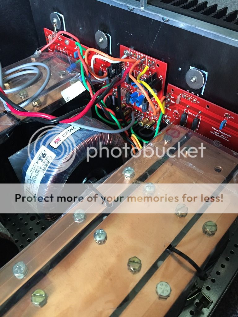
Its a bit tight in there...
So one bank of caps will be assigned to the new (second chassis) and some re arranging will help with air flow...though at present its all good temp wise. @.4v bias, offset is steady at just about +- .5mv
That is very cool, laverda!!
I'm new to this concept (using copper strips) so perhaps you can explain it to me:
Q1: I assume the copper strips are connecting a bank of caps? 12 caps in each bank?
Q2: How did you decide the copper thickness?
Q3: How do you stop the copper tarnishing? Spray with a clear coat?
Q4: The caps have screw connectors? What make caps are these and where do you buy them from?
Q5: What guage wire do you use to connect the copper strips to where the DC rails connect to?
Q6: Is that a complete amp ... or just the PSU?
Q7: If it's the complete (stereo - which you are going to split into monos) amp ... where are the heatsinks for the MOSFETs?
Thanks,
Andy
I can see one channel's two output devices bolted to the backplate of the heatsink in the pic you attached.
Can't you?
Aah, OK - thanks, Andrew. Now:
a) I see the fins of the heatsink, and
b) realise that the round things are large washers over the MOSFETS, to act as still more heatsinking. (Which is a great idea but not something I've ever done before.)
I can see one output device for the other channel, bolted to the same heatsink backplate.
I can see the fins of the heasink.
Yes, understood.
Thanks.
Andy
- Home
- Amplifiers
- Pass Labs
- F5 Turbo Builders Thread