Pass DIY Addict
Joined 2000
Paid Member
Out of interest, what is the preferred 22uF output cap other than a litic ?? Film/Polyprop?
TIA
You'll have a tough time finding anything but a litic in 22uF size, but I found this cap unnecessary after adding a cap in series with R14 to ground. Just lift the ground side of R14 and connect to the + lead of the cap and the - lead goes to ground. A bipolar cap would work here also but a standard electrolytic will work.
See the discussion here
You can find polypro, PIO, etc... caps in 22µF, but they are huge. But if Laverda has enough place in his box, he can try.
I understood that this output cap was a high-pass filter to prevent any DC to go to the next component (preamp, amp, etc...). I suppose it's possible to get rid of it if you have a input cap in your preamp, but I didn't know that the cpa in serie with R14 had the same effect.
Concerning this cap: given that R14 sets the gain, does adding a cap in serie with it changes something in the gain?
Last edited:
I like the mu metal shielding a nice touch and it does help.
Thanks Wayne.
You'll have a tough time finding anything but a litic in 22uF size, but I found this cap unnecessary after adding a cap in series with R14 to ground. Just lift the ground side of R14 and connect to the + lead of the cap and the - lead goes to ground. A bipolar cap would work here also but a standard electrolytic will work.
See the discussion here
...all clear now...I've already done the C in series with R14, so I'll whip out the 22uf and see....
") Many thanks.
Many thanks.Lately I have noticed that my Pearl 2 doubles as a tuner as among the background noise a radio station can be heard. Very low level but audible when a silent groove is played. This disappears when I disconnect the turntable. So I suspect it must have something to do with the new interconnect that was mounted on my Thorens (functions as an antenna?). Is there anything I can do to the Pearl to make it less susceptible to this?
Lately I have noticed that my Pearl 2 doubles as a tuner as among the background noise a radio station can be heard. Very low level but audible when a silent groove is played. This disappears when I disconnect the turntable. So I suspect it must have something to do with the new interconnect that was mounted on my Thorens (functions as an antenna?). Is there anything I can do to the Pearl to make it less susceptible to this?
If it disappears when you disconnect the TT, it's the TT picking up interference not the phono pre. The pre is just amplifying it. Look at the shielding of your phono from the cartridge all the way to the Pearl 2.
Cartridge is a Goldring Elite, so mc. I have clamp on ferrites on the cable (close to the RCA connector), they don't seem to help (but they may be the wrong type).
I'll try some variation in capacitance. If I manage to get a death metal station it might be mistaken for groove noise
I'll try some variation in capacitance. If I manage to get a death metal station it might be mistaken for groove noise
Can be the wire inductance resonates with the input capacitance of the high gfs JFETs at some high frequency. Like it happens with high gm tubes when without grid stoppers. If it resonates it picks RFI much easier.
To damp the gates with enough series resistance is no good in an MC phono because the gate stoppers will be higher than the cartridge's own Zout and they are going to add a significant noise component. Imagine that a 7-8mA IDSS K170BL can have about 50 Ohm RDS and a gate stopper could be at least 100 Ohm. It contributes double the noise of the JFET itself.
Tiny ring ferrite around each gate pin is the ultimate application but demands PCB level rework. I.e. find tiny beads, remove all input JFETs, pass their gate pins through beads, solder them back in.
10nF-100nF (preferably C0G) with shortest legs length possible connected from each channel's input RCA ring directly to chassis is a means to ground the shield carried RFI before it enters the PCB.
10nF-100nF across the input on PCB can be alternatively used if the cartridge type does not object.
Getting ""t2" correct
Clearly the components of the passive compensation network were "off".
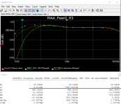
R11=6.81k, R12 909R, C17||20 333nF, C10,11,14 120nF. Both in simulation and actual practice the response deviated from the RIAA curve by an unacceptable amount. This is illustrated in the red curve of the graph below.
Using Lipshitz transform for a "1c" passive network, R11=6.81k, R12=990R, C17 = 302nF and C10,11,17=110nF use of these values more closely approximate the RIAA curve -- green line.
The "t2" pole discussion by Doug Self in Linear Audio Volume 7 left me wondering, what happened to the "t2" pole of 7950us for the Pearl?
If you want "t2" compensation, change coupling capacitors C12,C16 from 100nF to 39nF each. Illustrated in yellow.
Clearly the components of the passive compensation network were "off".
R11=6.81k, R12 909R, C17||20 333nF, C10,11,14 120nF. Both in simulation and actual practice the response deviated from the RIAA curve by an unacceptable amount. This is illustrated in the red curve of the graph below.
Using Lipshitz transform for a "1c" passive network, R11=6.81k, R12=990R, C17 = 302nF and C10,11,17=110nF use of these values more closely approximate the RIAA curve -- green line.
The "t2" pole discussion by Doug Self in Linear Audio Volume 7 left me wondering, what happened to the "t2" pole of 7950us for the Pearl?
If you want "t2" compensation, change coupling capacitors C12,C16 from 100nF to 39nF each. Illustrated in yellow.
Attachments
Jack,
I think you meant C14 in "Using Lipshitz transform for a "1c" passive network, R11=6.81k, R12=990R, C17 = 302nF and C10,11,14=110nF use of these values more closely approximate the RIAA curve -- green line."
I think you meant C14 in "Using Lipshitz transform for a "1c" passive network, R11=6.81k, R12=990R, C17 = 302nF and C10,11,14=110nF use of these values more closely approximate the RIAA curve -- green line."
Clearly the components of the passive compensation network were "off".
R11=6.81k, R12 909R, C17||20 333nF, C10,11,14 120nF. Both in simulation and actual practice the response deviated from the RIAA curve by an unacceptable amount. This is illustrated in the red curve of the graph below.
Using Lipshitz transform for a "1c" passive network, R11=6.81k, R12=990R, C17 = 302nF and C10,11,14=110nF use of these values more closely approximate the RIAA curve -- green line.
The "t2" pole discussion by Doug Self in Linear Audio Volume 7 left me wondering, what happened to the "t2" pole of 7950us for the Pearl?
If you want "t2" compensation, change coupling capacitors C12,C16 from 100nF to 39nF each. Illustrated in yellow.
Jack,
I think you meant C14 in "Using Lipshitz transform for a "1c" passive network, R11=6.81k, R12=990R, C17 = 302nF and C10,11,14=110nF use of these values more closely approximate the RIAA curve -- green line."
My eyesight must be failing!
C12,16 are the DC blocking caps which are reduced in value to effect the "t2" compensation.
I have the curves using the AP analyzer which confirm the simulation. Will post after the Christmas holiday.
- Home
- Amplifiers
- Pass Labs
- Building a Pearl 2