Oh GOOD! Although using an XLR connector is inviting trouble... I tend to use 4-pin Lemo or Tuchel connectors for such cables (using 2 pins for ground) so that mistakes cannot happen. I thought it looked suspiciously like my favourite 50Hz Test Oscillator ")
Attachments

Looks like the DC umbilical, not mains... ?
Yes, DC raw umbilical....back in the day I had the job of hooking up (making up) my sons bands xlr's. He used this vintage mic which needed 30vdc down a 25mtr run. It was always a enigma to me...why not use a modern mic? but he wouldn't be persuaded. XLRs are good, used world wide by all professional rockers....
'The mains cable' as used by a quality british audio manufacturing company as signal hook up from pre to power amps....
50hz tester, like it
Last edited:
So, move on
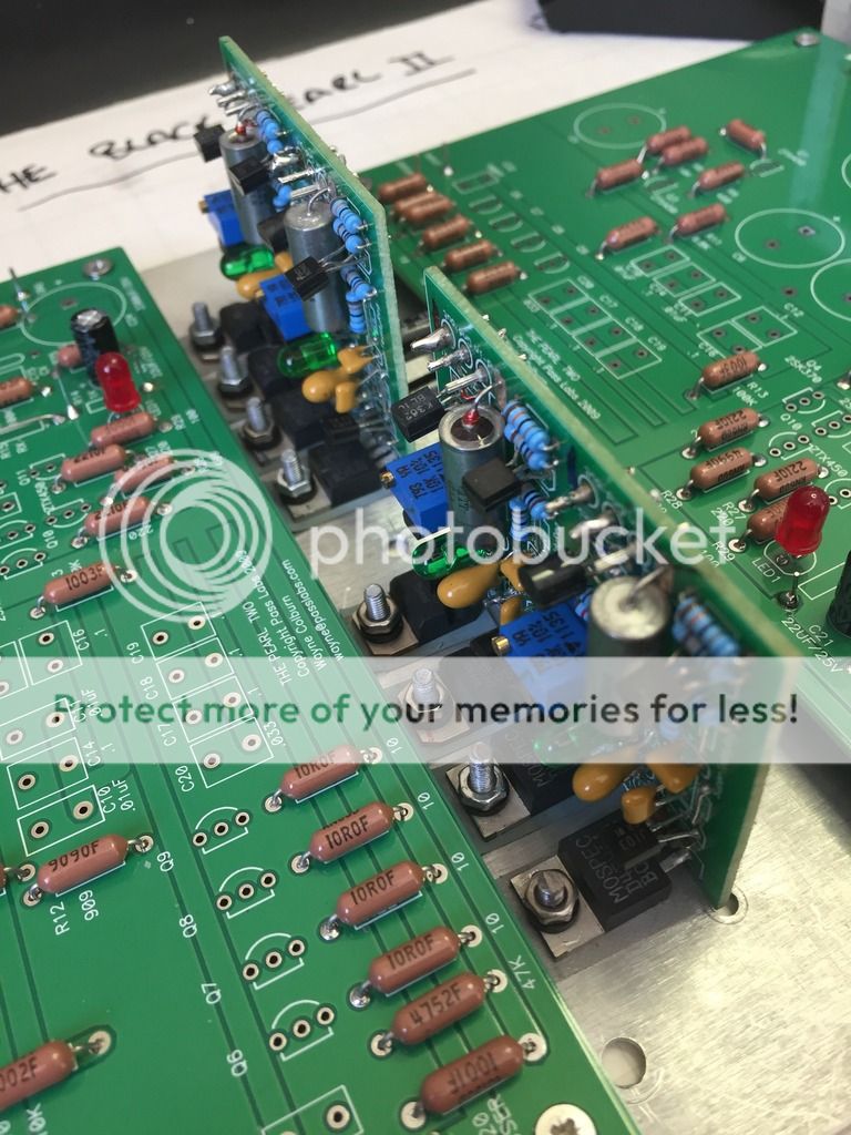
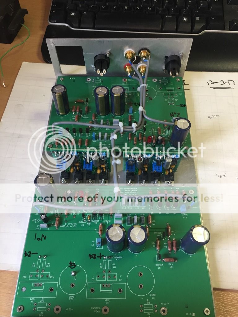
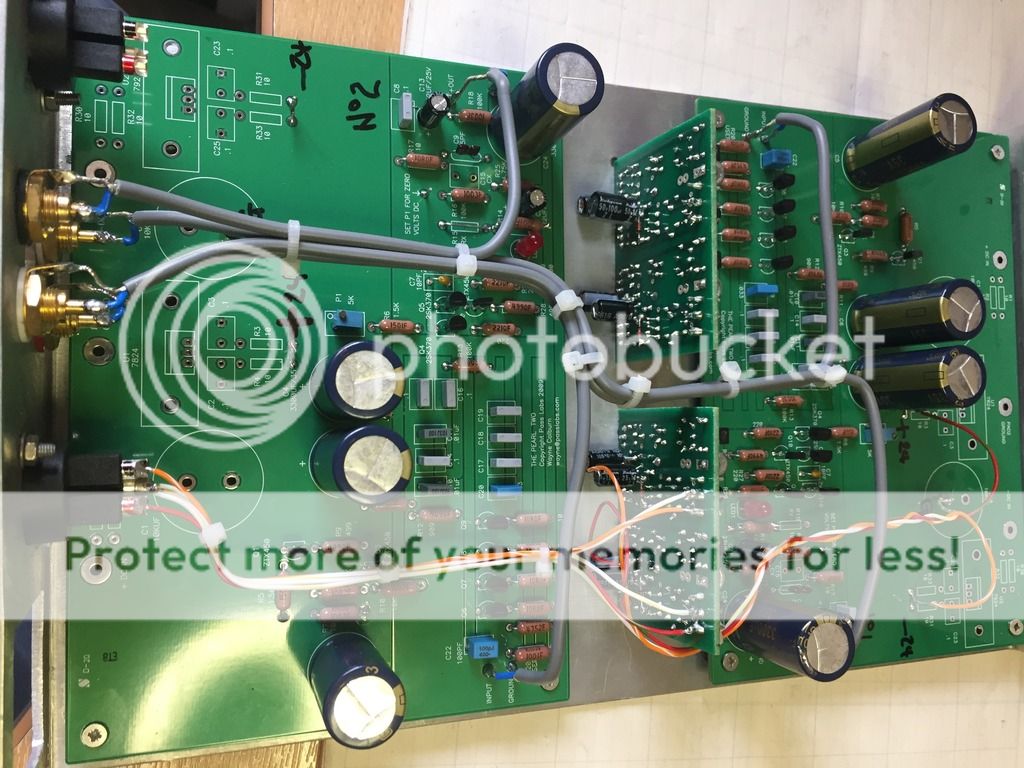
Ive installed the regs...using the chassis as a heat sink..
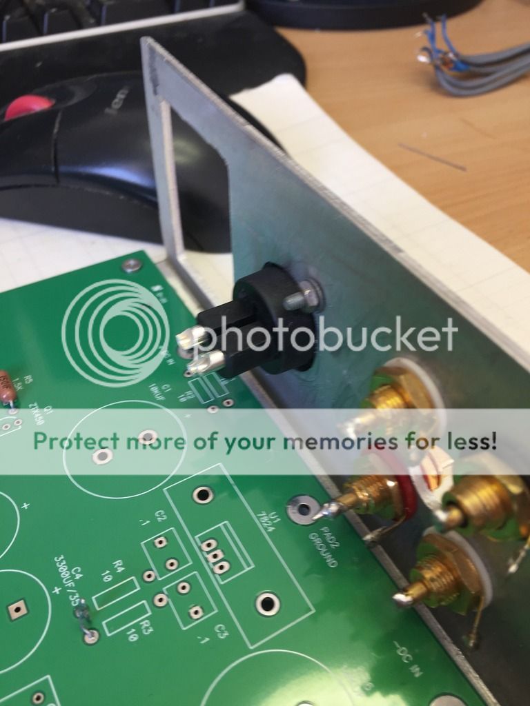
Fitted the XLR sockets for power to the Pearl case.
All looking good so far. No real problems..
A bit of wiring for signal in and out.
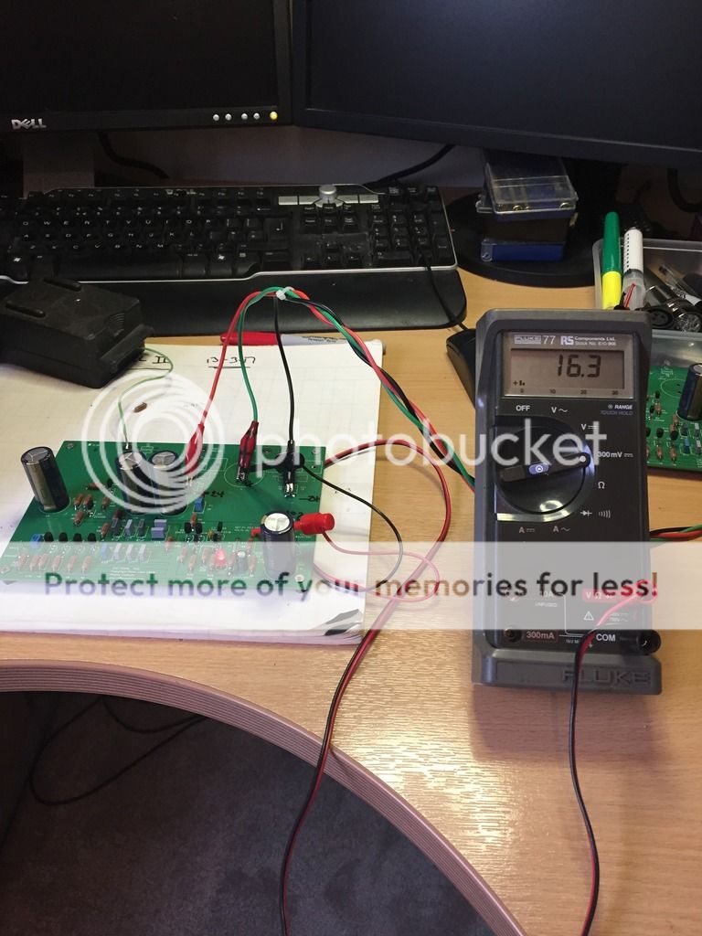
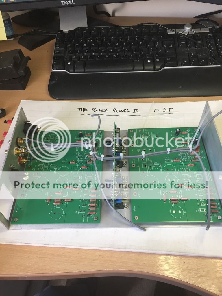
Completed the stuffing of the boards and power up. All going to plan. The offset it a pain though could not get it to 0v but done some homework and + -25mv is about what to expect.
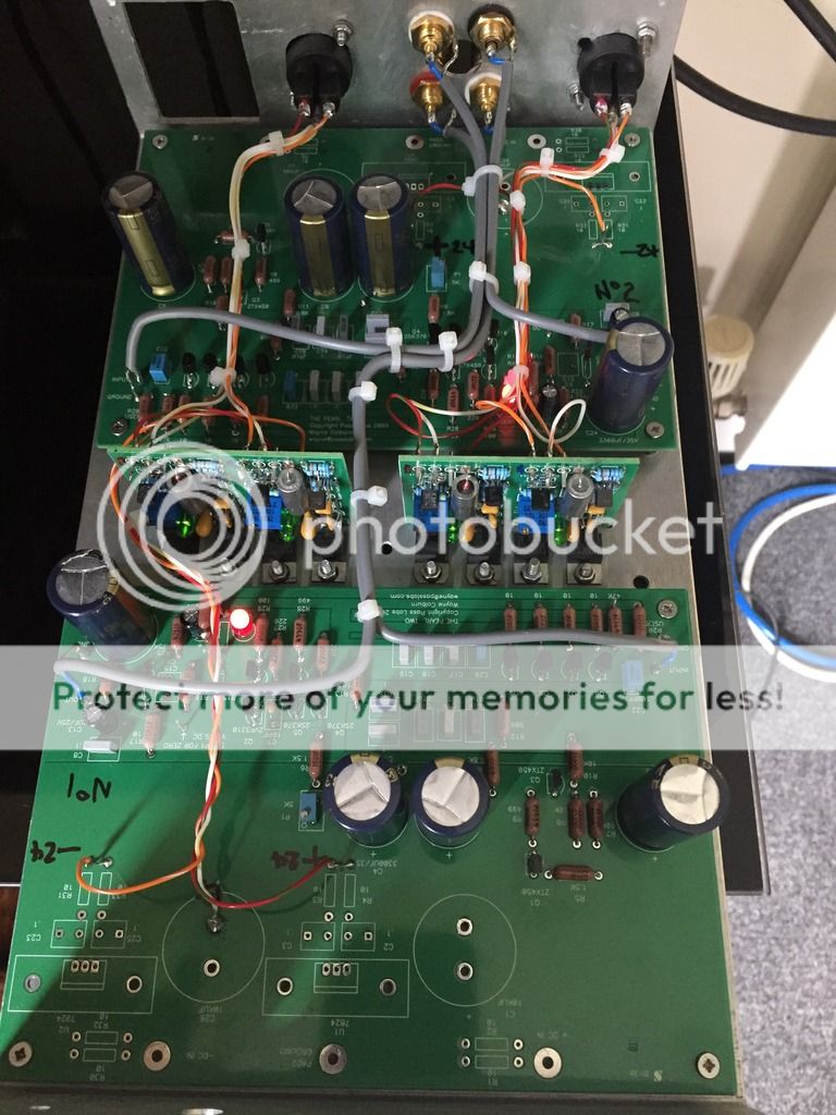
Final approach..
More to came....later today...
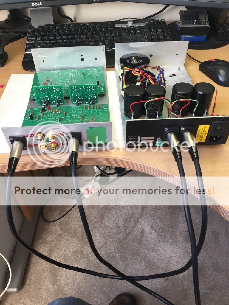
So we've now moved to the listening room and the first hook up...F...ME it works. No hummmm No hiss..My thanks must go to those who posted the answers to the problems they encountered during there builds.. Humm and Hiss.
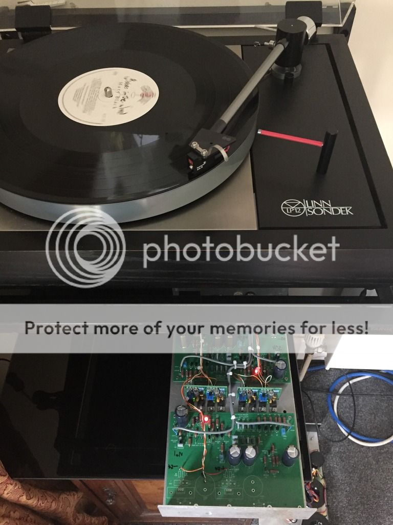
Sounding good, I'll return to the SQ later, (I'm still waiting for two transformers to complete the PSU design and only running on one side of the PSU for both boards) Than I can make a judgment on SQ I did have to swap out the 1K for 300Ohms to get some vol out of it. The PSU is on the floor just to the right in the photo.

Ive installed the regs...using the chassis as a heat sink..

Fitted the XLR sockets for power to the Pearl case.

All looking good so far. No real problems..

A bit of wiring for signal in and out.

Completed the stuffing of the boards and power up. All going to plan. The offset it a pain though could not get it to 0v but done some homework and + -25mv is about what to expect.

Final approach..

More to came....later today...

So we've now moved to the listening room and the first hook up...F...ME it works. No hummmm No hiss..My thanks must go to those who posted the answers to the problems they encountered during there builds.. Humm and Hiss.

Sounding good, I'll return to the SQ later, (I'm still waiting for two transformers to complete the PSU design and only running on one side of the PSU for both boards) Than I can make a judgment on SQ I did have to swap out the 1K for 300Ohms to get some vol out of it. The PSU is on the floor just to the right in the photo.
Last edited:
anyone have a part number for:
100 pF
10 pF
5 pF
red LED
thanks!!! - was trying to find WIMA equivalents for the pF caps - but got confused...
you may not need the 10pf, most just leave it out. Its a 'Hiss' generator. I put one in but snipped one leg just in case...Not needed.


OK I'll bite...what's with all the transformers?
See 848, One transformer per rail (galvanic isolation) 'its way way over the top' but I had two 0 22 0 22 transformers anyway along with the T net caps, rectifiers and most everything else other than the Pearl boards, I had to buy some MKP caps for the Pearl Boards.
A note on 4 Poles Smoothing caps if used as intended the earth return 0V travels through the cap effectually isolating/filtering any "mains borne noise" on the 0v mains earth.. Some like em, some do not. I like them.
From the get go it was clear this was a great sounding head amp but one channel produced a strange 'distortion' it worked but was un-listenable and was getting worse as time went on. Investigation relieved the offset on that channels board would creep up + or - 'volts' not mv over a period of hours.
Thinking that my PSU and super regs may be an issue I installed the stock regs on the boards but to no-avail. errr.
Mindful of the caution with regard to the 3310 static issue I just changed it on the offending board. The offset was now in a steady state or as best as one would expect over time (a few hours)..
Things were now much better, and no distortion, and sounding very good indeed. ye ha.
So now it was time to re-instate the super regs as per my original design....WOW, now we have a superb sounding head/phono amp, a big improvement on the stock on board regs. IMO
Now I have superb clarity and texture with additional musicality which was always the target.
To recap (no pun):- the raw PSU consists of 4 x 80va 2 x 0 22 transformers (one per rail) to MBR20200 rectifiers each rail having 10000uf T Net caps, these is in one case, feeding 4 super teddy regs set for + - 24v feeding the Pearl II boards these in a second case.
Yet again my thanks to 6L6
Last edited:
MM Revisited
Greetings. I've been a lurker on this thread for a while but this is my first post.
I built a Pearl 2 a couple years ago and really love it. A friend of mine wants one but he wants it for a moving magnet cartridge. I've been through this thread a couple times and can find a couple references to lowering the gain. The suggestions are to increase R14 or decrease R16. One spot indicates that decreasing R16 from 100k to 50k will drop the gain to 454dB. Is this the best approach? Seems like it might be still too much gain. Is it better to bypass the first gain stage? Any thoughts or suggestions will be most welcome.
Thank you.
hirscwi:
I just finished building a Pearl II with a high output Moving Magnet (5 mV)
I reduced the second stage gain by decreasing R16 to 50k.
It still had too much gain so I reduced the first stage gain by increasing R21-R24 from 10R to 20R.
To my ear this is getting close for my high output MM and there is still plenty of gain in my line level preamp to accommodate a lower output MM.
These are simple changes to the BOM that are easy to change back if they are not optimal for your buddy's cartridge.
Good luck on the second build.
Thanks very much for the information and the fast response.
6L6, I have a question concerning your grounding scheme (sorry if it has been asked before):
You isolate the grouding post from the back panel, then you connect it to a hole in the chassis. Why not connect the ground to the chassis via the grounding post (by not isolate it)?
Thanks.
You isolate the grouding post from the back panel, then you connect it to a hole in the chassis. Why not connect the ground to the chassis via the grounding post (by not isolate it)?
Thanks.
That is a good question.
If you connect all points - the PCB grounds from the center of the boards, and the chassis to the grounding post, then the post itself becomes the least potential.
The chassis and all the connections float around the Pearl RIAA boards. The chassis is just one point that connects to ground, centered at the post.
- Home
- Amplifiers
- Pass Labs
- Building a Pearl 2