That is a good question.
If you connect all points - the PCB grounds from the center of the boards, and the chassis to the grounding post, then the post itself becomes the least potential.
The chassis and all the connections float around the Pearl RIAA boards. The chassis is just one point that connects to ground, centered at the post.
I think I understand. Thanks.
")
Picture of a central grounding post
Folkdeath:
Below is a picture (sorry it is kind of blurry) of the central ground post in my Pearl build - from post #2730 of the Pearl Two thread.
It is the brass bolt just to the right of the diode bridge in the picture.
Chassis ground (from the wall outlet) and one side of the "grounding diode bridge" land there.
The chassis is also grounded at that point by a stainless steel star washer under the bottom ring terminal.
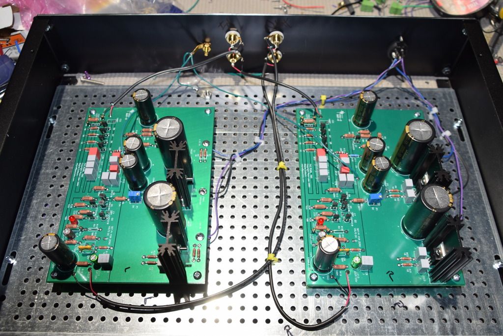
I used a one box solution for PSU and Pearl boards but if you have an outboard PSU then you would need to run one ground wire from chassis ground in the PSU to the center grounding post and a separate wire from the center point between the PSU caps to the ground on each of the Pearl boards.
The tonearm ground (white terminal post in the back), and the ground for each of the Pearl boards are routed separately and land at the center point between the two UPSU boards, i.e. at the Neutral point between the Positive and Negative capacitors in the PSU.
I hope this helps but let me know if you have any questions.
Folkdeath:
Below is a picture (sorry it is kind of blurry) of the central ground post in my Pearl build - from post #2730 of the Pearl Two thread.
It is the brass bolt just to the right of the diode bridge in the picture.
Chassis ground (from the wall outlet) and one side of the "grounding diode bridge" land there.
The chassis is also grounded at that point by a stainless steel star washer under the bottom ring terminal.
I used a one box solution for PSU and Pearl boards but if you have an outboard PSU then you would need to run one ground wire from chassis ground in the PSU to the center grounding post and a separate wire from the center point between the PSU caps to the ground on each of the Pearl boards.
The tonearm ground (white terminal post in the back), and the ground for each of the Pearl boards are routed separately and land at the center point between the two UPSU boards, i.e. at the Neutral point between the Positive and Negative capacitors in the PSU.
I hope this helps but let me know if you have any questions.
Das Proekt Pearl two soweit habe ich abgeschlossen. Es lauft super. Ich uberlege mich einen fuenften sk170 dazu einloeten. Ich benutze Pearl zu einemOrtofon mc30 super mkii und 0,2mV ist schon eine Herausvorderung.
Was sollte ich in schematik noch aendern, dass due ganze funktioniert. Von DC-Versorgung habe ich reichlich, also 100W.
Was sollte ich in schematik noch aendern, dass due ganze funktioniert. Von DC-Versorgung habe ich reichlich, also 100W.
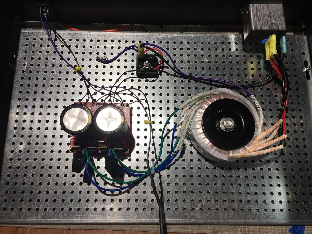
An externally hosted image should be here but it was not working when we last tested it.
The inside of Power supply
I just finished my PSU.

It works OK, but I measured +/-38V.
I didn't test the transformer when I bought it a few months ago, but when I checked this evening, I discovered that it gives 28V instead of the 24V it should...
Will 38V be OK for the Pearl2 boards?
If not, is there any option other than buying a new transformer?
It works OK, but I measured +/-38V.
I didn't test the transformer when I bought it a few months ago, but when I checked this evening, I discovered that it gives 28V instead of the 24V it should...
Will 38V be OK for the Pearl2 boards?
If not, is there any option other than buying a new transformer?
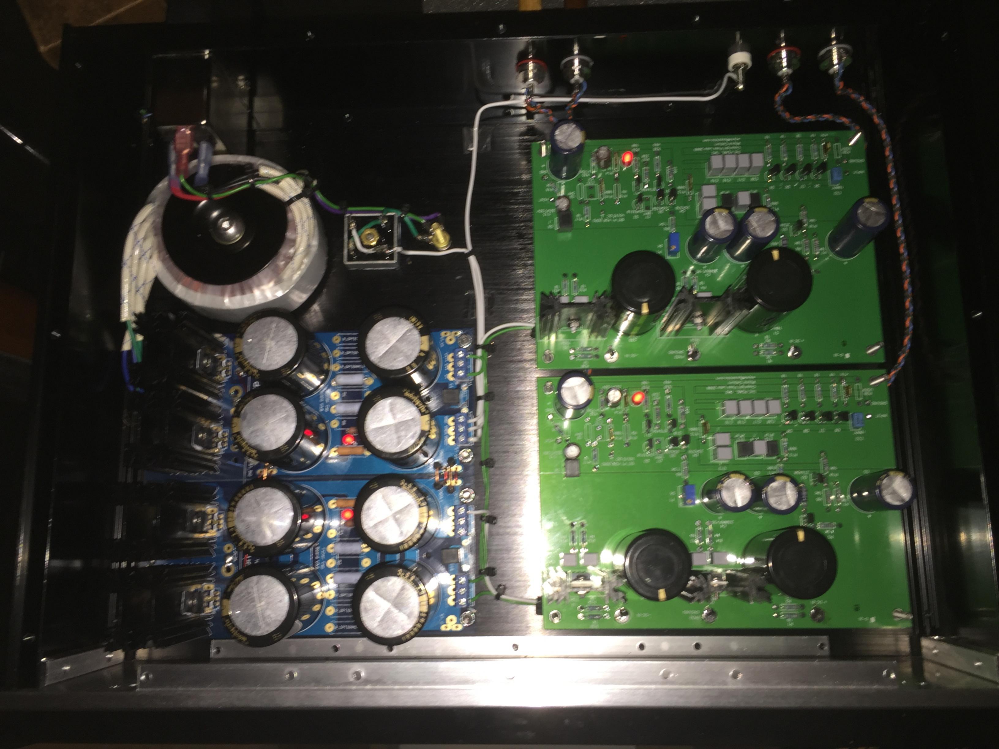
I finally finished my Pearl2 on wednesday evening.


I found the offset adjustment rather tricky, even with a cap in serie with R14. It changed when I removed the screwdriver from the trimmer, so I had to adjust-remove hand-read voltage-adjust again-remove my hand again-etc...
Well it seems to be OK now.
I didn't have time to listen to it, I will try tomorrow.
I finally finished my Pearl2 on wednesday evening.
View attachment 619334
View attachment 619335
I found the offset adjustment rather tricky, even with a cap in serie with R14. It changed when I removed the screwdriver from the trimmer, so I had to adjust-remove hand-read voltage-adjust again-remove my hand again-etc...
Well it seems to be OK now.
I didn't have time to listen to it, I will try tomorrow.
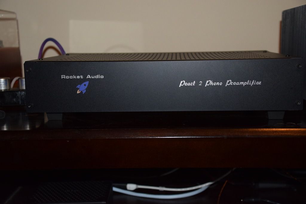
Another good looking build...
What did you line the pearl case with? Thanks
Thanks.
The white thing in the case is self-adhesive mu-metal sheet.
Thought it was, just checking. Thanks.
I have a itch to make a mu-metal cover 'shroud' for a few transformers I have in various bits of kit where the transformer is close to the circuits..just to see if I can hear any perceivable difference.
Hi,
Where did you get the self-adhesive mu-metal sheet? I want to install it to my pearl 2.
Regards
Where did you get the self-adhesive mu-metal sheet? I want to install it to my pearl 2.
Regards
Thanks.
The white thing in the case is self-adhesive mu-metal sheet.
- Home
- Amplifiers
- Pass Labs
- Building a Pearl 2