Andrew,
I do not see anywhere in the manual where it shows an unbalanced connector can be connected to the amp (either written or a picture of this).
Unfortunately I am not going to be able to modify the amp input. That is why I was wondering if I would lose any benefit of the B1 by either coming out of the B1 with an RCA and using a RCA to XLR connector to the amp OR going RCA from the B1 into my Onkyo CD inputs (which I am doing now). I hope all of that makes sense. Thanks.
James

James, there's no benefit in placing a B1 if you don't remove the Onkyo for the signal path. Not that it's a bad pre, but having 2 preamps at the same time is silly.
The DCB1 outputs a singled-ended signal (aka: not balanced). Use an adapter from RCA to XLR, or make yourself a proper cable.
Regards,
Regi
The DCB1 outputs a singled-ended signal (aka: not balanced). Use an adapter from RCA to XLR, or make yourself a proper cable.
Regards,
Regi
Turn on thump
Hi,
I have completed my B1 and it seems to work fine apart from a loud turn on thump. It is being tested with a chipamp and an old pair of speakers. I have a single pole switch on the DC power in for the +ve. Pulling out the power plug also causes a thump but probably not so loud.
I checked the DC on the output and it reads 0.15V and decreases to 0 in around 2 mins. The diode (1N914) has the bar towards the middle of the board.
Should I have a 2 pole switch for ground and +v?. I am using a laptop power supply with 19.5V.
Thanks,
Kffern
the B1 has a DC blocking capacitor on it's output.
This cap must charge to it's final operating voltage after start up. This will send a pulse to the next stage.
Similarly the capacitor must discharge after switching off. This will send another pulse to the next stage.
There are disadvantages to single ended ClassA, this is one of them.
This cap must charge to it's final operating voltage after start up. This will send a pulse to the next stage.
Similarly the capacitor must discharge after switching off. This will send another pulse to the next stage.
There are disadvantages to single ended ClassA, this is one of them.
Have you sequenced turn on/off? Or tried turning it on w/volume at zero?
Turning it on with volume down makes no difference.
I normally do follow the same sequence but thought wanted to be sure. Don't want to blow my Tannoys. using the wall swith on the SMPS is the best as the power comes on slowly.
Thanks,
Kffern
what I suggested should work to ameliorate this...
And is standard protocol with separates in any event. As has been stated 2 or three times. Why would anyone purposefully turn off or on a pre amp with the power amp already powered up anyway?
Good practice would be not to fool with any thing upstream while the power amp is on. Turning it off first keeps various transients at shut down of upstream components from being amplified and sent to the speakers.
Russellc
Last edited:
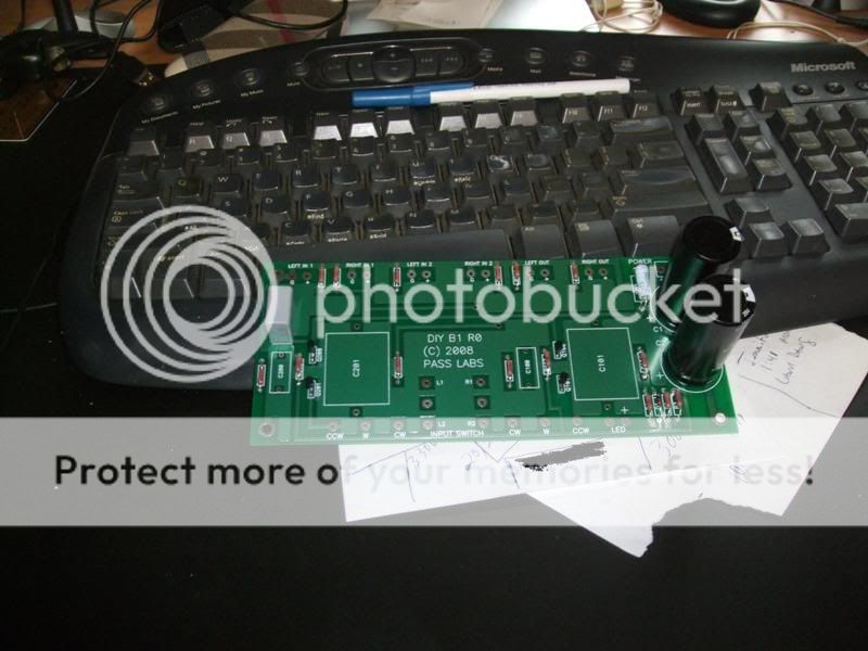
Here is my progress so far. Just resistors, jfets and some caps. I wanted to wait on getting the enclosure before running any of the wires for everything else. The picture is not the best so I apologize about that.
James
An externally hosted image should be here but it was not working when we last tested it.
James
Hey Guys
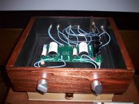
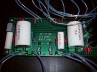
Just thought I would post a couple shots of finished B1.
Nice B1. I'm a little curious about the output wiring...it looks like it is split into 2 sets of connectors but I could be wrong. Would you mind explaining???
Thanks,
I ran 2 more outputs parallel off first set RCA outs.
for Subs, It works great.no drop in volume at all.
Mr Pass told me this would work,and it does perfectly.
for Subs, It works great.no drop in volume at all.
Mr Pass told me this would work,and it does perfectly.
Nice B1. I'm a little curious about the output wiring...it looks like it is split into 2 sets of connectors but I could be wrong. Would you mind explaining???
Thanks,
I ran 2 more outputs parallel off first set RCA outs.
for Subs, It works great.no drop in volume at all.
Mr Pass told me this would work,and it does perfectly.
can you post a picture to see how it is done?
Thanks
can you post a picture to see how it is done?
Thanks
Bigaudioscotto's pictures are already posted above in post 2573.
The pic is posted at above 2573.
It is very simple just come off of your existing output RCA
jacks.solder a wire from ground to ground on another RCA.
then simply solder a wire from center pin to center pin .
all you are doing is wiring 2 more RCA parallel off existing Jacks.
just look close at the picture the smallest wire is feeding
the Sub outputs.
can you post a picture to see how it is done?
Thanks
- Home
- Amplifiers
- Pass Labs
- B1 Buffer Preamp