thanh1973 said:Do you have any idea what I might be doing wrong?
Or is this a common problem with simulators?
common problems with simulators .............. less and less brain-time .....
and less gadgets really made

thanh1973 said:Do you have any idea what I might be doing wrong?
Or is this a common problem with simulators?
Jfet model not that efficient maybe.
I have this one. Changing the Beta, Idss changes. Try to see what happens (if it is not the same already).
.model J2sk170 NJF(Beta=59.86m Rs=4.151 Rd=4.151 Betatce=-.5 Lambda=1.923m
+ Vto=-.5024 Vtotc=-2.5m Cgd=20p M=.3805 Pb=.4746 Fc=.5
+ Cgs=25.48p Isr=84.77p Nr=2 Is=8.477p N=1 Xti=3 Alpha=10u Vk=100
+ Kf=111.3E-18 Af=1)
.model J2sk170 NJF(Beta=59.86m Rs=4.151 Rd=4.151 Betatce=-.5 Lambda=1.923m
+ Vto=-.5024 Vtotc=-2.5m Cgd=20p M=.3805 Pb=.4746 Fc=.5
+ Cgs=25.48p Isr=84.77p Nr=2 Is=8.477p N=1 Xti=3 Alpha=10u Vk=100
+ Kf=111.3E-18 Af=1)
Hi tanh, I havent simulated this circuit but I for one think it would display more h3 than second, playing around with values should make h2 dissapear. I dont think the guys that get h2 to be above have the exact same circuit as in the pass paper, and if I remember correctly NP himself said it would be predominantly h3.
Well I hope so.
I am learning heaps at the moment using LTspice - changing values or components looking at the effects, determining dc offset, bias currents, input impedance, and also looking at the distortion profile.
It has also been a source of motivation to try tweeking things where as before, I would be totally relying on ohers experience or guessing.
Anyway, I hope as you say it is predominantly H3, or all confidence I have in simulators will be lost.
Unless I can find the source of this discrepancy.

Thanks Nelson
OK then hopefully I have made a mistake somewhere.
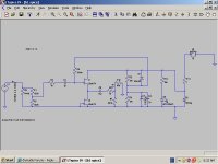
Can someone check the way I have drawn the circuit.
I am a little unsure about the signal ground/return and output ground/return, and the DC power ground/return.
Any help would be most appreciated.
Thanks
OK then hopefully I have made a mistake somewhere.
Can someone check the way I have drawn the circuit.
I am a little unsure about the signal ground/return and output ground/return, and the DC power ground/return.
Any help would be most appreciated.
Thanks
Attachments
thanh1973 said:Thanks Nelson
OK then hopefully I have made a mistake somewhere.
Can someone check the way I have drawn the circuit.
I am a little unsure about the signal ground/return and output ground/return, and the DC power ground/return.
Any help would be most appreciated.
Thanks
You do not have things setup completely for an FFT with LT Spice. Try adding the following directives.
.tran 0 30m 0.1u
.step param C list .100u .10100u
.option plotwinsize=0
Test at 1000Hz.
If you want to learn more about LT Spice. Try the forum for it on groups.yahoo.com. I am unable to help you further. I just copied the above from an example I found there. It works for me.
Jim

Mr. Pass
I read a post by you that mentioned using the AP1 and some other attenuator after the source and before the amp with a buffer or pre inbetween. I cant for the life of me find it now. You talked about maybe having just a few different resistances to choose from before the buffer/pre and then after it to have, I think, the AP1.
Is this to help 'rectify' any source output/amp input impedance issues or what is the reason?
I think this was with a BOSOZ.
Thanks
Uriah
udailey said:Mr. Pass
I read a post by you that mentioned using the AP1 and some other attenuator after the source and before the amp with a buffer or pre inbetween. I cant for the life of me find it now. You talked about maybe having just a few different resistances to choose from before the buffer/pre and then after it to have, I think, the AP1.
Is this to help 'rectify' any source output/amp input impedance issues or what is the reason?
I think this was with a BOSOZ.
Thanks
Uriah
AP1 is measuring gadget , almost capable of computing 42 .
we don't ( we - spoiled kids ) even need to know exactly what's that beast ..........
anyway - I can just imagine using it as attenuator
- Home
- Amplifiers
- Pass Labs
- B1 Buffer Preamp