Yes. I'm even somewhat familiar with the Ayrton-Perry winding techniques.
But a foil resistor can be relatively inexpensive and compact, which is important in high bandwidth applications (like the staircase output of a DAC).
I don't see how being inexpensive is valuable for high "bandwidth" (I assume you mean frequency) applications. Even further, I'd need to see proof (as in actual evidence) that the inductance of normal WW resistor causes some kind of problem when used as an IV resistor.
If you think small size was paramount, then use a SMD RF resistor. I don't think it matters so I wouldn't do that.
Very interesting. Thank you !
Please do not laugh at me
But what about "linearity" with very low level signal ?
I suppose that a good feedback resistor should be exceptionally linear
Maybe it is also a noise related issue ? the low the noise the higher the linearity ?
Which Resista series have you tested ?
Because Holco are rare and Caddock are very expensive
Thank you very much again
Regards,
gino
The old stock ones I got from Michael Percy Audio.
There is less distortion with lower level signals. You really should check out the article.
Yes the voltage dependent noise also shows up in the tests. Lower distortion resistors tend to have less noise. The best bang for the buck was the Xicons, sold by Mouser. However as processes change with time, there is no guarantee.
The Dale are low cost and the oversized military specification parts are the equal of the Caddocks.
Last edited:
Even further, I'd need to see proof (as in actual evidence) that the inductance of normal WW resistor causes some kind of problem when used as an IV resistor.
Not inductance, but rather physical size and necessity of traces to match. It might work fine, but since inexpensive metal foils are small and will certainly work fine, I'll leave it to you to find out if the alternatives won't cause issues.
The old stock ones I got from Michael Percy Audio.
There is less distortion with lower level signals. You really should check out the article.
Yes the voltage dependent noise also shows up in the tests. Lower distortion resistors tend to have less noise. The best bang for the buck was the Xicons, sold by Mouser.
However as processes change with time, there is no guarantee.
The Dale are low cost and the oversized military specification parts are the equal of the Caddocks
Thanks a lot for the advice
The brands you mention are indeed very often recommended
Regards,
g
Not inductance, but rather physical size and necessity of traces to match. It might work fine, but since inexpensive metal foils are small and will certainly work fine, I'll leave it to you to find out if the alternatives won't cause issues.
When are metal foil resistors ever inexpensive, especially Z-foils?
Did you mean metal film? Preferably lowest Tc available (25ppm or less)
We have known for over a century how to wire wind a (very) low inductance resistor, even low value wirewounds.
I once made the mistake of using a low value Mills MRA-5 "non inductive" wirewound as a programming resistor on a CCS feeding a shunt regulator I was building. I used it because I had it in stock and it was the correct value. The regulator oscillated wildly until I replaced this with a metal film R of the same value. I suppose the problem could relate to size but the Mills wasn't THAT much larger than the .6 watt R used to replace it.
I guess "inexpensive" is relative.
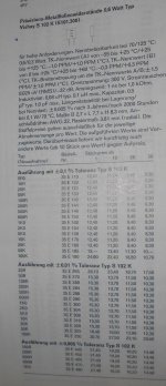
(1989, German DM, ex 14% sales tax)
Attachments
Not inductance, but rather physical size and necessity of traces to match. It might work fine, but since inexpensive metal foils are small and will certainly work fine, I'll leave it to you to find out if the alternatives won't cause issues.
Sy,
IS there a simple explanation as to trace/resistor match statement. I am new to it all, but PCB design, especially. How big of an effect can trace size play on overall performance?
When are metal foil resistors ever inexpensive, especially Z-foils?
Did you mean metal film? Preferably lowest Tc available (25ppm or less)
I believe you can get thin film SMD resistors in 10ppm for a dollar or less.
Actually, I modeled a current generator in Tina with a 20uH inductor (with 47 ohm resistance) as an IV converter and it's not good. The Bode plot shows a flat response to about 10kHz, then rising rapidly from there. So, I non-inductive resistor would be much preferable in that location.
Sy,
IS there a simple explanation as to trace/resistor match statement. I am new to it all, but PCB design, especially. How big of an effect can trace size play on overall performance?
As usual, it depends.
 Think of the resistances as part of the circuit and see if they are significant- for example, in a regulator sense line (very low current), they're not terribly important, but between the regulator output and the sampling point (high current), they matter a great deal since they cause a sampling error. I saw one preamp this weekend where every trace was laid out for perfect matching of lengths and widths side to side in a balanced circuit as well as channel to channel. Overkill, for sure, but it was really nice from an esthetic standpoint (which I do not discount!).
If memory serves, Analog Devices did a very nice publication on this. It might be worthwhile to poke around their website to find it (mine is a hard copy).
And I'll repeat something I've admitted to before- I absolutely suck at PCB design and leave it to talented folks like jackinnj or pinkmouse to do for me.
A super nice fellow at Axpona, Douglas Hurlbut, who did a very good phono preamp (one of the five figure jobs). He walked me through the design, answered all my questions, and seemed pretty pleased that someone "got" the small clever things he had done.
Dynamic Sounds Associates - Phono II
Dynamic Sounds Associates - Phono II
Modern cad programs
Duh, they already did a couple of decades ago, just not as inexpensive.
At university, I had to design and optimise a pcb layout, exercise part of a simulation class.
Sucker also had an auto-route button, aka dumbie trap.
(ship design includes the general electrical layout, design of the main switchboard, knowledge of generators, transformers, rectifiers, thyristors, power factors, etc.)
Saturn PCB Design - PCB Via Current | PCB Trace Width | Differential Pair Calculator | PCB Impedance
Every one who does PCB design should have this on their desktop, it will give you all the data you require for your traces and vias.
Yep a nice looking PCB will generaly be good electronicly, as making things match and look nice is the icing on the cake.
Regulator feedback inputs (especially SMPS controllers) are very high impedance inputs, so the trace from the potential divider to this pin should be as short as possible, otherwise you can pick up noise, think of it as the most important trace for any PSU controller.
The other thing that you must think about is loop area when doing a PCB, that means you need to think of every signal as a pair of routes, the signal trace and its return path (the gnd trace, or better still for low level a plane).
Just want to say that I tried with nice results resistors quite cheap bought from RS Components.
I am quite sure that the brand was Welwyn. The 0.5W series in particular.
RS still sells these parts.
Has anyone else tried them as well ?
They had quite big legs ... and as i said very cheap indeed. Like 1-2 euro for ten
As general purpose ... maybe out from the feedback path
But now that I have checked they have a better and more expensive series that looks incredibly similar to Holco resistors (and these are very good. I have two series attenuators built with them and like the sound a lot indeed).
The TCR=15ppm series.
Regards,
gino
Last edited:
- Status
- Not open for further replies.
- Home
- Member Areas
- The Lounge
- Resistor Sound Quality?