Ok Joe & Bolserst,
Seem to be time to order some components to be able to do the required tests later on. Still struggleling with the wave guide build as things tend to come between.
Thanks.
Seem to be time to order some components to be able to do the required tests later on. Still struggleling with the wave guide build as things tend to come between.
Thanks.
I think i will start with the 1273 post order in testing before reversing anything. Stage 1: 33Ohm resistors, Stage 2: midbass LCR link + parallell resistor and removing the second LCR to the bass drives, and Stage 3: Incert the bass driver adjusted LCR. Thanks for reminding me of that post, it is now in the "most interesting posts.docx".
Elsinore Mark 5 progress...
Here is a family of modeled responses, see below.
All at 2 Metres and Blue "O" on axis, Green "15" off axis and Red "30" of axis.
It suggest that toe in can be quite critical and around 20 degrees may be the smoothest.
Please ignore plotting above 30 KHz.
Cheers, Joe
.
Here is a family of modeled responses, see below.
All at 2 Metres and Blue "O" on axis, Green "15" off axis and Red "30" of axis.
It suggest that toe in can be quite critical and around 20 degrees may be the smoothest.
Please ignore plotting above 30 KHz.
Cheers, Joe
.
Attachments

Joe, have you attenuated the breakup node? That 4-10khz response rise lines up with the breakup node on the sb drivers
Joe, have you attenuated the breakup node? That 4-10khz response rise lines up with the breakup node on the sb drivers
It's not exactly what it looks like.
They are accentuated by the fact that this driver has very low inductance and hence looks to be at disadvantaged compared to most others drivers but a few. It looks worse than it is. The CSD plots don't show up any significant modes where the straight FR response would seem to indicate.
Just please trust me on this for now, the gremlins you may imagine and the gremlins I want to avoid, seem to be different.
I am now listening to first iteration of Mk6 and I am very pleased. It does in some ways measure less well that Mk5 and that is not something I am overly concerned with - what I am hearing now shows I have been well justified.
Every speaker design involves compromises, but more importantly, it also has to have a set of priorities, even before you start. If one has different set of priorities, then you may well end up with making decisions you otherwise would not.
I have my reasons, but I want to avoid at all cost any parallel Zobel or LCR networks in parallel with the Voice Coils. They just kill clarity while making a measurement looking more respectable.
The key objective here is noise. In time I will elaborate more - but there are odd compromises made here that you would not normally see in a commercial speaker - but you will in time see this approach used because there are compelling reasons.
Right now I have a big smile on my face - the Mark 6 is what has put it there. And what is more, the modelling has been so spot on that I have not had to change any values that was predicted. The High-Pass from Mark 5 to the Tweeter is totally unchanged, the topology has stayed the same and only values tweaked to accommodate the change in drivers.
BTW, and this was true with Mark 5 and even more so with Mark 6, that the toe-in is far more critical than more conventional designs. I recommend listening 15-20 degrees off axis. If the room is on the dead side, then toe more in towards the listener and vice versa.
I now realise I should have emphasized this much more when Mark 5 came out and I will now be more emphatic about it with Mark 6.
Cheers, Joe
PS: Please see CSD plot below - very rigid fibre cones and aberrant modes at 14.3KHz and 19KHz - high enough not to be a worry - I believe that CSD plot goes some way to explain what I am hearing. Very stiff and clean cone that pushes modes up and gets emphasised at a higher frequency. It seems to get the right result where it is needed.
Please also note that the non-Referenced CSD plot is clean.
Attachments


Last edited:
the toe-in is far more critical than more conventional designs. I recommend listening 15-20 degrees off axis. If the room is on the dead side, then toe more in towards the listener and vice versa.
+1. cannot believe it took me months to figure that one out. toed in to cross 2-3 feet in the front they got a new life 😀. and room coverage became pretty uniform. (this is of course for the "original" with HDSs; btw the tweet is just an excellent unit!).
I am glad that Joe is back having more fun with the design. not sure though that the choice of driver is an improvement. how relevant can low inductance and nonlinear d. be for a design with maximized area and small overall movement? isn't that a design criteria for OBs? (on the other hand, if I had a whole bunch of drivers from B&W speakers, even their low end, I would be tempted to try and put together an improved version around the same design concept. I made some A-B comparisons in clarity on selected tracks).
So good luck with the redesign. and thanks again for the original version
 .
.I originally had mine toed in to intersect at about two feet behind my listening position and found that with certain types of music they could sound slightly over bright. I have recently set them to intersect at about 10 feet behind me and there is quite a marked difference in sound. It is now a more laid back sound. They certainly have a small sweet spot but it is very sweet!!
not sure though that the choice of driver is an improvement...
It is. The details will be published here during next week.
The only way that there was going to be a Mark 6, or rather, the only rationale is that it should be better than Mark 5 and I can confirm that IMO it is.
Crossover topology is the same, only that some values have been changed - so it should be possible to update earlier Crossovers.
The problem is fitting the SB drivers and flush mount them where the Peerless HDS drivers were - the actual cut-out is the same within a millimetre - but it is the routing and flush mounting that will be trickier. Of course, if you make them from scratch it will be easier. Use a router and jig to do the job.
Cheers, Joe
.
The details will be published here during next week.
We are almost getting there.
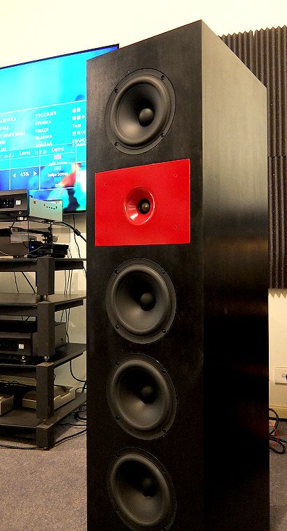
Please see the picture below - these will belong to Paris as soon as a second pair is done, he will be picking them on. I need then to have mine working as guests coming need to see and hear a working pair. Mine are a older pair upgraded to Mk6 - they are a pair with the older square Waveguides.
Once that is done, then the first thing posted will be the new Crossover. We are now talking days.
Anyone in the vicinity are welcome to come around for a listen. Those who have so far have been mighty impressed - that is all I want to say for now as far as sound quality - the ones that build the Mk6 from scratch and those that upgrade the older Mk5, let them have a say from a fresh viewpoint without too much telegraphing from me.
For those upgrading from Mk5 to Mk6, the only real problem is going to be mounting new drivers, the Crossover changes are manageable.
Cheers, Joe
.
Attachments

Last edited:
ANNOUNCING ELSINORE MARK 6 DETAILS:
We start with the Heart of the Elsinore Speaker:
As can be seen, the old Mark 5 Crossover can be changed- please look at the 'asterisks' where the values have differed. Note that while 20mH is specified, if you have 18mh then keep them, but do not go above or below those two values.
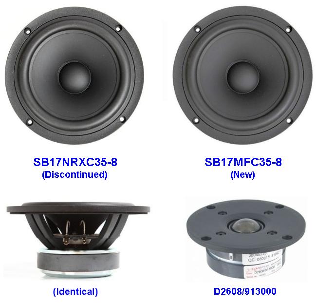
The of big difference and maybe the most problematic for upgrading old Mark 5 to Mark 6 - the new SB Acoustics Mid/Bass drivers needs to be recessed - the recess required is 7mm and out diameter 174mm - the same actual cut-out of 146mm is the same as before:
So those are the constructional details - now for modelling and measurement details:
Note these are modeled results, now for the actual measurements:
I do not believe any commercial speakers measure like that when it comes to system impedance and electrical current phase angle.
Now an in-room response using Pink Noise and 1/3rd Octave RTA - please not this includes the room in the response and at the listening position:
Below 1KHz, the peaks and troughs, which are also related to room modes, to nicely even out - and note the bass response is flat down to at least 30 Hertz.
Now of course the obligatory picture of the drivers:
Finally:
The construction details have now been updated on the website: www.customanalogue.com/elsinore/elsinore_index.htm
Cheers, Joe
.
We start with the Heart of the Elsinore Speaker:
As can be seen, the old Mark 5 Crossover can be changed- please look at the 'asterisks' where the values have differed. Note that while 20mH is specified, if you have 18mh then keep them, but do not go above or below those two values.
The of big difference and maybe the most problematic for upgrading old Mark 5 to Mark 6 - the new SB Acoustics Mid/Bass drivers needs to be recessed - the recess required is 7mm and out diameter 174mm - the same actual cut-out of 146mm is the same as before:
So those are the constructional details - now for modelling and measurement details:
Note these are modeled results, now for the actual measurements:
I do not believe any commercial speakers measure like that when it comes to system impedance and electrical current phase angle.
Now an in-room response using Pink Noise and 1/3rd Octave RTA - please not this includes the room in the response and at the listening position:
Below 1KHz, the peaks and troughs, which are also related to room modes, to nicely even out - and note the bass response is flat down to at least 30 Hertz.
Now of course the obligatory picture of the drivers:
Finally:
The construction details have now been updated on the website: www.customanalogue.com/elsinore/elsinore_index.htm
Cheers, Joe
.
Last edited:
Congratulations!
I can assure you that you will see commercial speakers with such flat impedance and phase. It is my beleif that is the way it should be.
I can assure you that you will see commercial speakers with such flat impedance and phase. It is my beleif that is the way it should be.
Has anyone run the Elsinore's as a 2 way with a ribbon? Have DBX drive rack PA+ that will be crossover. Can ad more amps if needed. Always liked the sound of an Infinity Emit and picked up a few Fountek Neo CD 2.0's to morph the Elsinores.
Has anyone run the Elsinore's as a 2 way with a ribbon? Have DBX drive rack PA+ that will be crossover. Can ad more amps if needed. Always liked the sound of an Infinity Emit and picked up a few Fountek Neo CD 2.0's to morph the Elsinores.
it wont be Elsinore 🙂
Has anyone run the Elsinore's as a 2 way with a ribbon?
I have measured many ribbons and they need to be very large or they produce a lot of distortion at the lower end of their pass band. That is why some limit them to super-tweeter status, like Bill Dudleston of Legacy Audio does (I know a major distributor). But if somebody could design one with and integrated Waveguide that would massively reduce distortion for a given size, then indeed I would find that interesting. The waveguide would recess the driver and ribbons draw a very clean current and have no dominant Fs type resonance that cones and domes have. But it would then have to be tried to see if it would even work. Got any idea how much work that would be?
But alas, not seen a ribbon tweeter like that anyway.
Cheers, Joe
.
Elsinore Mark 6 Addendum:
Many will have the same problem that I had, Mark 5 or earlier box and to bring them up-to-date.
With the HDS 6.5" drivers, if they were not recessed into the box, if the hole of 146mm were just cut and then the basket/flange of the drivers covering up the edges, then this solution I used is for you to consider.
If you recessed them, them you would need a filler - I would use a type used for cars - in different countries they have different names for them, like some call it bog filler. It is essentially a filler that you add a small amount of hardener to - and you only have a few minutes to apply.
The solution is to make a "bridge" that can sit across the hole - it needs to be very tight, and use a bit of wood glue to set it in well. Then we need to find the middle of the hole and mark it on the "bridge" - and this will be what the centre of the route jig will use for a diameter off 174mm and 7mm deep, see diagrams below.
These are the recess dimensions:
The work in progress:
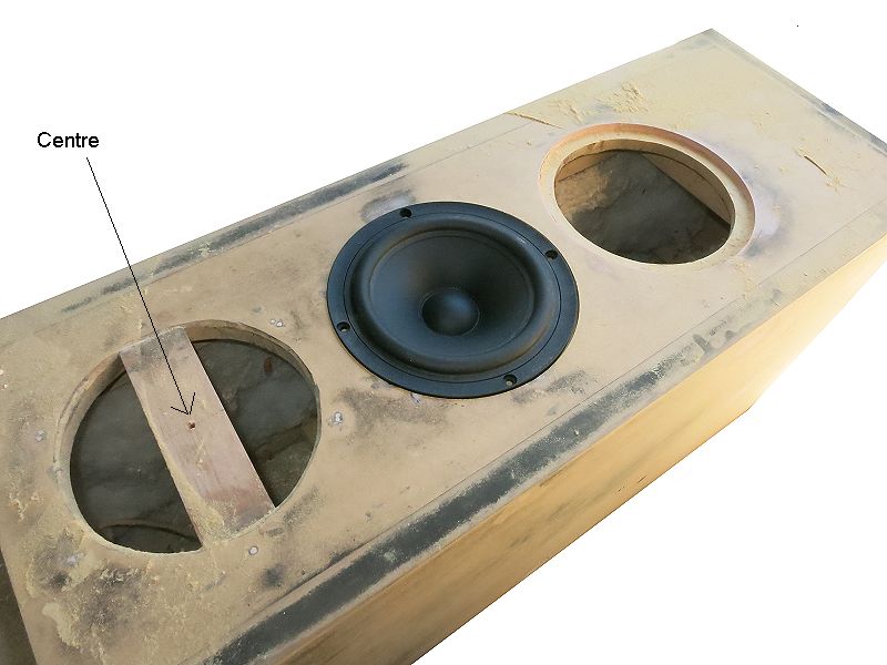
Here two have already been done and the third is ready for the router.
Here are the dimensions of the "bridge" I used:
I only shave just enough of the corners with a rasp, to make it a super tight fit and literally used a hammer to make it fit.
The bridge should be just flush and if anything slightly lower and it must not protrude beyond the front panel.
I used a Jasper jig. Some are able to k=make their own - it's up to you - but work slowly and carefully and you will get there.
Here is what they finally looked like:
Cheers, Joe
.
Many will have the same problem that I had, Mark 5 or earlier box and to bring them up-to-date.
With the HDS 6.5" drivers, if they were not recessed into the box, if the hole of 146mm were just cut and then the basket/flange of the drivers covering up the edges, then this solution I used is for you to consider.
If you recessed them, them you would need a filler - I would use a type used for cars - in different countries they have different names for them, like some call it bog filler. It is essentially a filler that you add a small amount of hardener to - and you only have a few minutes to apply.
The solution is to make a "bridge" that can sit across the hole - it needs to be very tight, and use a bit of wood glue to set it in well. Then we need to find the middle of the hole and mark it on the "bridge" - and this will be what the centre of the route jig will use for a diameter off 174mm and 7mm deep, see diagrams below.
These are the recess dimensions:
The work in progress:
Here two have already been done and the third is ready for the router.
Here are the dimensions of the "bridge" I used:
I only shave just enough of the corners with a rasp, to make it a super tight fit and literally used a hammer to make it fit.
The bridge should be just flush and if anything slightly lower and it must not protrude beyond the front panel.
I used a Jasper jig. Some are able to k=make their own - it's up to you - but work slowly and carefully and you will get there.
Here is what they finally looked like:
Cheers, Joe
.
Hi Joe,
Did the new rebate for the speakers remove the old speaker screw holes.
Or do they need to be bogged up before routing.
By calculation its a close call.
Also if 2 x 10mh with rcd of 3.6R was used could the resistor be eliminated.
Cheers
Did the new rebate for the speakers remove the old speaker screw holes.
Or do they need to be bogged up before routing.
By calculation its a close call.
Also if 2 x 10mh with rcd of 3.6R was used could the resistor be eliminated.
Cheers
- Home
- Loudspeakers
- Multi-Way
- The "Elsinore Project" Thread