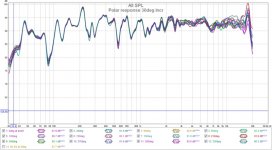
Polar response
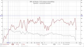
Despite ongoing tuning I though I'd recheck the polar response. I have polar symmetry (mostly) except for the 3 support posts which should only interfere at higher frequencies.
The measurements are taken at 1m, 30deg step, at mid disc height (0.87m) and with room acoustics using 1/12oct smoothing. Minor EQ was done to lower 3 bumps (-3db) at [370, 660, 4600Hz]. The 15Khz bump was left because I can't hear it") . I used FDW-4 to locate bumps (not shown).
. I used FDW-4 to locate bumps (not shown).
The support posts do have an effect at higher frequencies. However, any wall reflections will have a spectral content similar to incident sound and moving (horizontally) does not change the timbre.
Despite ongoing tuning I though I'd recheck the polar response. I have polar symmetry (mostly) except for the 3 support posts which should only interfere at higher frequencies.
The measurements are taken at 1m, 30deg step, at mid disc height (0.87m) and with room acoustics using 1/12oct smoothing. Minor EQ was done to lower 3 bumps (-3db) at [370, 660, 4600Hz]. The 15Khz bump was left because I can't hear it
. I used FDW-4 to locate bumps (not shown).The support posts do have an effect at higher frequencies. However, any wall reflections will have a spectral content similar to incident sound and moving (horizontally) does not change the timbre.
Attachments
...What part is causing the "weird" alert. What should or not be there?
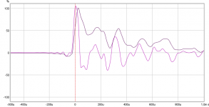
Think most of the weird alert is in pre/attack side that it goes down to almost minus 6o procent, and in my imagination looks like woofer is reversed and fire relative early interrupted by late sharp tweeter impulse but my imagination could be wrong of what's going on there.
How about measurement chain, is it clean and strait or is there more or less some sample rate conversion taking place at multiple places between measurement program/operating system/hardware, if that's case could explain some and we should just live with the look of it : )
OK, thanks. I'll run a few experiments to see if I can identify the source of the activity before the +ve impulse spike.
Run a measurement of the drivers separately but with the crossover in place so either disconnect or short out one at a time to see if the impulse looks more correct that way, by looking at the phase through the crossover region you can see if that is causing time alignment issues.
Could be a measurement issue but would be easier to see with only one driver at a time.
Tweeter should be a strong sharp pulse with minimal over / under shoot, woofer will be a much slower rise.
It is the sharp down before the peak and the shape that makes it look like a phase or alignment issue to me too.
Run a measurement of the drivers separately but with the crossover in place so either disconnect or short out one at a time to see if the impulse looks more correct that way, by looking at the phase through the crossover region you can see if that is causing time alignment issues.
Could be a measurement issue but would be easier to see with only one driver at a time.
Tweeter should be a strong sharp pulse with minimal over / under shoot, woofer will be a much slower rise.
It is the sharp down before the peak and the shape that makes it look like a phase or alignment issue to me too.
OK I see what you and @byrtt are looking at. The driver test with everything, but the other driver connected, is easy to do. I do this normally as well, but usually don't look the IR.
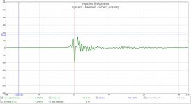
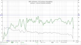
With the correct polarity(s), I get an FR with mag and phase that looks correct and the weird impulse (previous). I have usually inverted this IR as I expected it to go +ve. If I reverse the tweeter polarity I get a hole in the FR at the XO crossover and the phase is twisted but the IR looks better.
Have a look, I'll continue investigating when I'm back (fri).
Attachments
-
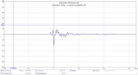 tweeter only IR correct pol.jpg59 KB · Views: 61
 -
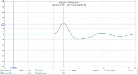 woofer only IR correct pol.jpg57.2 KB · Views: 62
 -
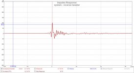 system - reverse tweeter IR.jpg60 KB · Views: 234
 -
 system - reversed tweeter.jpg88.3 KB · Views: 232
 -
 system - correct tweeter IR.jpg60 KB · Views: 240
 -
 system - correct tweeter.jpg87.5 KB · Views: 240
...Have a look, I'll continue investigating when I'm back (fri).
Ha ha (fri) can mean free from work in Danish, any genes or relationship to Denmark
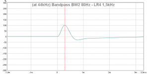
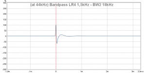
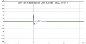
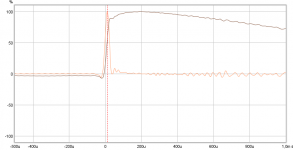
Thanks those IR it looks woofer is by the book but tweeter is weird so wonder if chain has minor problems in HF area or sweep settings into REW is cause, find below synthetic perfect IR in close to same XY axis for BW2 80Hz-LR4 1,5kHz and LR4 1,5kHz-BW2 18kHz.
Attachments
Last edited:
The tweeter and woofer polarities are relative to get the same response. I would rather have the tweeter in positive polarity as measured and then set the woofer to get the response you are after. But maybe that is just because it looks more like it should rather than sounding any different.
Sometimes diaphragms are put in backwards or the terminals are marked incorrectly so looking at an IR is the best way of knowing if you have the polarity correct unless you can see the cone move by applying a battery to the terminals to determine it visually. Pretty hard with a compression driver.
I suspect the slightly funky pre-ring before the main peak is due to the measurement chain, are you still using your PC soundcard as mic amp and input?
Ha ha (fri) can mean free from work in Danish, any genes or relationship to Denmark
Thanks those IR it looks woofer is by the book but tweeter is weird so wonder if chain has minor problems in HF area or sweep settings into REW is cause, find below synthetic perfect IR in close to same XY axis for BW2 80Hz-LR4 1,5kHz and LR4 1,5kHz-BW2 18kHz.
Thanks for the reference graphs. I agree there is a problem in the chain somewhere, but I don't think its from a reversed driver, otherwise the FR would be weird as well.
No Danish that I know of
just a happy coincidence.The tweeter and woofer polarities are relative to get the same response. I would rather have the tweeter in positive polarity as measured and then set the woofer to get the response you are after. But maybe that is just because it looks more like it should rather than sounding any different.
Sometimes diaphragms are put in backwards or the terminals are marked incorrectly so looking at an IR is the best way of knowing if you have the polarity correct unless you can see the cone move by applying a battery to the terminals to determine it visually. Pretty hard with a compression driver.
I don't think its a reversed driver, because the FR looks strange when I reverse a driver. I'll recheck the entire path with a meter to be sure.
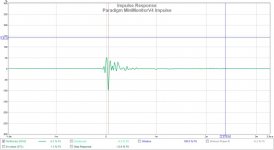
However, there is an easy way to divide the problem. I connected a known good commercial speaker(s) using the same setup to see if its impulse shows the same issue. This can determine if there's a common denominator or the speaker. Graph#1 and graph#2 have the same problem. Same chain, different speakers, so its not the speaker. The problem is elsewhere in the chain.
I suspect the slightly funky pre-ring before the main peak is due to the measurement chain, are you still using your PC soundcard as mic amp and input?
Yes, I still use the PC soundcard with an omni mic. That is now suspect as well and may have taken me as far as it can. I will be buying the UMIK mic to replace it. There are still other variables I still need to check. Still looking.
Attachments
Think recall from past seen a chain that had glitch trouble always presenting IR pointing in negative direction but its SR was going in positive direction showing polarity was right, if that's the case here it should be easy to check on "Impulse" tab by turning on SR too and see if they go same direction as below.
Attachments
Cone shape question...
Hi Don, thanks for posting your progress! Like you, I am interested in modifying a driver dispersion pattern, not necessarily to 360d, (more like 140 to 160d) but I feel your approach is similar to what I want to attempt (sometime in the future). You've probably already seen this, but I'm linking to it for other readers...Cloning a $3200 Speaker for $400
I'm curious about how you selected the various cone shapes to test? - I noted that the woofer cone is slightly convex and the tweeter cone is slightly concave - Is there something about the frequencies being reflected that led you to those shapes or was it purely trial and error?
Thanks!
Six - Minneapolis.
Various cone shapes with moderate different slopes and curvatures were tried to reproduce the baseline open air response at the disc edge with the cone in place. Graph#2 shows that below 5Khz the response is not that sensitive to the cone shape adjustments. Above 5Khz, small changes in the slope or the gap can make a significant difference. I think this will be an ABEC exercise eventually.
Hi Don, thanks for posting your progress! Like you, I am interested in modifying a driver dispersion pattern, not necessarily to 360d, (more like 140 to 160d) but I feel your approach is similar to what I want to attempt (sometime in the future). You've probably already seen this, but I'm linking to it for other readers...Cloning a $3200 Speaker for $400
I'm curious about how you selected the various cone shapes to test? - I noted that the woofer cone is slightly convex and the tweeter cone is slightly concave - Is there something about the frequencies being reflected that led you to those shapes or was it purely trial and error?
Thanks!
Six - Minneapolis.
The cone shapes were calculated at post #92 OmniDirectional - work in progress . I have 2 surfaces (discs) that the wave travels between before exiting. I assumed a spherical wavefront between the surfaces and determined the shape required to make it expand at an exponential rate. The woofer is between a flat disc and a cone. The tweeter is between 2 cones initially, then finally a disc and a cone. Then the inside path length and the outside path lengths are made equal. So this makes the discs in the middle smaller. A spreadsheet is used to try to find a solution that satisfies these requirements. Then the profile is transferred to polystyrene using a fixture at post #150 OmniDirectional - work in progress. The transfer is not perfect, so at testing I made minor shape changes based on the behaviour I was seeing.
Think recall from past seen a chain that had glitch trouble always presenting IR pointing in negative direction but its SR was going in positive direction showing polarity was right, if that's the case here it should be easy to check on "Impulse" tab by turning on SR too and see if they go same direction as below.
That's a good suggestion, check the SR with the IR. Unfortunately, the deeper I dig, the weirder it gets. I'll post some results that try to eliminate possible causes.
There are may amplifiers that turn phase 180 degrees...
Thanks, it looks like I have one of those.
Next question, are you using a single or two amplifiers for the proto? Phase polarity per se doesn't matter, but the real acoustic phase combination does.
Another issue you might have is that either your acoustic slopes are not symmetrical or time delay is not right. Timing/delay can be easily seen from step response of two units playing, polarity "right" and reversed, then overlay these two graphs.
Another issue you might have is that either your acoustic slopes are not symmetrical or time delay is not right. Timing/delay can be easily seen from step response of two units playing, polarity "right" and reversed, then overlay these two graphs.
weird IR investigation
As pointed out by @fluid and @byrtt, I seem to have a weird IR. I have tried the same config with different speakers ( OmniDirectional - work in progress ) and it exists regardless of speaker for my existing setup. These are some more tests to try to isolate the problem.
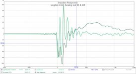
Test#1 : Trying a soundcard analog output and different amp to see if the IR and SR are aligned. Graph #1 show the response of a computer speaker Logitech L523. It uses the analog outputs and has its own amp. The IR and SR both go in the same direction and have a clean start. This tells me the omni mic and sound card input are not causing the problem.
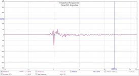
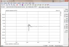
Test#2 : Comparing the results from ARTA to REW. Both show the same results for the OmniV5. ARTA uses shaped pink noise and REW uses swept sine. Graph#2 is from ARTA OmniV5 IR. So, its not the S/W.
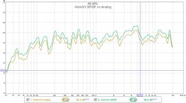
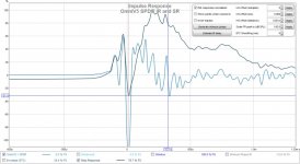
Test#3 : Compare the results of the PC sound card SPDIF output and analog output as connected to the Yamaha RXV659. The FR, SR, IR is the same on both which eliminates the output type as the cause. However notice the notch in the SR which coincides with the IR and it happens for either input to this amp (RXV659). More investigation here.
As pointed out by @fluid and @byrtt, I seem to have a weird IR. I have tried the same config with different speakers ( OmniDirectional - work in progress ) and it exists regardless of speaker for my existing setup. These are some more tests to try to isolate the problem.
Test#1 : Trying a soundcard analog output and different amp to see if the IR and SR are aligned. Graph #1 show the response of a computer speaker Logitech L523. It uses the analog outputs and has its own amp. The IR and SR both go in the same direction and have a clean start. This tells me the omni mic and sound card input are not causing the problem.
Test#2 : Comparing the results from ARTA to REW. Both show the same results for the OmniV5. ARTA uses shaped pink noise and REW uses swept sine. Graph#2 is from ARTA OmniV5 IR. So, its not the S/W.
Test#3 : Compare the results of the PC sound card SPDIF output and analog output as connected to the Yamaha RXV659. The FR, SR, IR is the same on both which eliminates the output type as the cause. However notice the notch in the SR which coincides with the IR and it happens for either input to this amp (RXV659). More investigation here.
Attachments
Next question, are you using a single or two amplifiers for the proto? Phase polarity per se doesn't matter, but the real acoustic phase combination does.
Another issue you might have is that either your acoustic slopes are not symmetrical or time delay is not right. Timing/delay can be easily seen from step response of two units playing, polarity "right" and reversed, then overlay these two graphs.
Its a single amp (yamaha RXV659) driving both in a stereo configuration. The speakers have passive LR4, Zobels, notch filters. I've tried reversing the tweeter and the woofer but the FR ends up having a large hole when a polarity is reversed. I also get this IR behaviour with a commercial speaker so I don't think its the speaker or driver polarity. Based on some recent tests, I now think its amp, but I'm still running tests.
Even acoustic domain never gets as clean curves as in electric and synthetic domain there looks be seriously HF transition glitch problems in chain somewhere, below is also in acoustic domain when it looks worst and things starts to be corrected by the book, good luck in troubleshooting.
Attachments
It's a little strange as the step of the logitech generally follows the direction of the IR but it is such a mess it is not much confirmation. It also looks inverted.
You could test with just your woofer, without the crossover and see if everything goes in the right direction.
Try a loopback of the soundcard to see what that looks like, you could measure the amp through REW by making sure that the volume is low enough that you are getting less than 1V out of it, then it won't kill your soundcard. That would tell you if you are getting a polarity reversal from the electronics.
I had one in my ES9018 DAC with polarity set to positive phase I got a negative impulse, fortunately the DAC has a setting to change the phase so I reversed it.
Could Equalizer APO being doing something or another part of Windows as you are not using drivers with exclusive access to the hardware?
- Home
- Loudspeakers
- Multi-Way
- OmniDirectional - work in progress