It looks You have a lot of problems with those cones - so why such a cone at all?
I understand that You'd like to put the tweeter above the woofer but in that case why not just aim a compact neodymium tweeter up and the "cone" required in such configuration (to mount the tweeter in) would be much smaller and creating less problems. Actually it could be in a shape and material minimizing reflections which are utterly undesirable.
Perhaps it wouldn't look so cool like a Duevel clone but definitely less problems.
Yes, there have been many problems, but I am getting closer with each iteration. I understand that many people try to eliminate all reflections, and many prefer open fields and anachoic chambers. However, my goal on this speaker is to have the same freq response 360deg around the speaker and use the room. So polar symmetry is preferred. Cones are the only way that I know of that can transfer the radiation patterns from piston type drivers into the radial pattern that I want.
Up to 10K the response is just like most waveguides/horns you get a greater efficiency as you go down in frequency until the waveguide loses pattern control. The bump at 15K is not quite so normal but could well be breakup. Is it there in the manufacturers data?
The shape of the tip will be acting as a phase plug so different shapes there might be worth looking at.
Yes, there is a data sheet https://www.fane-international.com/downloads/Fane-CD130-DS240316.pdf and it looks much better than my FR. That being said, on closer examination, they have in small light print at the bottom "custom horn 90x40 used in testing" . My circular waveguide has no FR performance prediction Dayton Audio H10RW 10" Round Waveguide 1-3/8"- 18 TPI . In fairness it was the only round WG that could go down to 1.6KHz that I could find.
I like that phase plug idea, thanks. The cone tip is 5cm from the CD bug screen and the waveguide has minimal expansion at that point. I can replace tips easily, and its worth a try.
Yes, there have been many problems, but I am getting closer with each iteration. I understand that many people try to eliminate all reflections, and many prefer open fields and anachoic chambers. However, my goal on this speaker is to have the same freq response 360deg around the speaker and use the room. So polar symmetry is preferred. Cones are the only way that I know of that can transfer the radiation patterns from piston type drivers into the radial pattern that I want.
"360deg around the speaker" - means 360 horizontal? But one does not need any cones for that.
360 vertical is another story BUT nobody needs that because floor reflection is rather undesirable
"360deg around the speaker" - means 360 horizontal? But one does not need any cones for that.
360 vertical is another story BUT nobody needs that because floor reflection is rather undesirable
Yes, its 360deg horizontal radiation.
True, there are some other options. I could use multiple small full range drivers arranged in a circle. Or maybe a compression driver using a multicellular horn arranged with radial outputs.
I went with a 2way system, one driver per cone to make it simple. Sound originates from the same center axis, both drivers are 20cm from the mid disk exit (time alignment), and an LR4 XO (phase alignment).
yeah, but I wonder what's exactly the advantage of pointing the tweeter downwards into a waveguide instead of pointing it upwards with a little cone perhaps if someone deems it necessary for 2 top octaves?
in other words what's the advantage of Duevel over Morrison/Hegeman? other than coolosity
yeah, but I wonder what's exactly the advantage of pointing the tweeter downwards into a waveguide instead of pointing it upwards with a little cone perhaps if someone deems it necessary for 2 top octaves?
The orientation of the driver is still vertical (up or down) and the wavefront needs to be converted to horizontal and preferably toroidal in shape. By pointing the LF and HF driver toward each other, the exit path is nearly the same (at mid disc). Stacking them to both point vertical would offset the LF and HF exit points. Nesting them would reduce height but still leave the outputs offset.
In my case the tweeter takes care of >1.5Khz so I do need it. If I can get decent performance to 12KHz I'd be happy. In my tests the measurements are the standard 20-20Khz and that's a much wider range than my hearing capabilities.
in other words what's the advantage of Duevel over Morrison/Hegeman? other than coolosity
Thanks for the pointer to the Morrison/Hegeman, they are new to me. They act like the Dueval Planets model using a sphere above the driver. The other Duevals use cones and compression drivers and I think that latter method has the better performance.
You could actually use many shapes then EQ out the problems. Sound will bend and bounce around everything. But I was trying to minimize the "help" they needed. I would like the performance after the cone to be the same as the on axis driver (ie. acoustic transparent cone).
I think the cones offer a better explanation of steering the wavefront from vertical to horizontal. In my previous tests, a blunt surface above the driver will work for low freq but then as the driver gets directional you get a reflection and often standing waves. The shapes I use do have some reasoning to them OmniDirectional - work in progress and I also use ABEC BEM to understand the wavefront.
The orientation of the driver is still vertical (up or down) and the wavefront needs to be converted to horizontal and preferably toroidal in shape. By pointing the LF and HF driver toward each other, the exit path is nearly the same (at mid disc). Stacking them to both point vertical would offset the LF and HF exit points.
so it's about time aligment - I see You believe in advantage of time alignment
Dueval Planets model using a sphere above the driver. The other Duevals use cones and compression drivers and I think that latter method has the better performance.
Inferior performance of Planets is due to their asymmetry. Morrison speakers have symmetrical configuration.
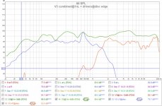
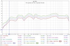
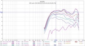
Omni V5 - system tests
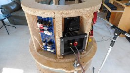
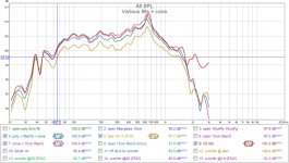
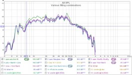
I've added RLC notch filters (pic#1) at 630Hz and 2.5Khz to reduce the "humps" in the FR. The graphs below have no EQ (s/w) added, and they include room acoustics. I've warmed up to using FDW 4 cycle in the FR graphs using far field measurements.
I've included graphs for driver+system, power levels, distortion, and impulse.
There is still a bump at 630Hz but it seems to show in the near field but not the far field. Even with the woofer disconnected, for the HF near field measurement, the WG+CD can excite the lower chamber. Looks like some more damping is required.
I could not find electrical parameters to model a compression driver with a wave guide. The manufacturer does not provide them and I don't think the T/S model applies. A simple 5 or so electrical component equivalent or even a polynomial(s) set would allow me to SPICE the HF response flatter.
No matter for now. I'm in a position to start optimizing for the room and my listening position.
Attachments
Hornresp can model your waveguide and CD with T/S parameters although they can be difficult to obtain for CD's too. But it won't model the effects of your cones.
Have you measured the waveguide and CD on a baffle or in free air without the cones to get a baseline?
If you are using a screw on CD then you might want to look at the throat transition area. They can be improved with modelling clay or similar and it can have a big impact on the VHF response.
Try some fibreglass or felt in you enclosure, even egg crate foam works much better than acrylic to damp resonances.
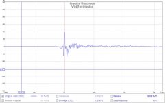
For me four cycles is too smoothed 6 or 8 is more useful, the impulse is weird, have you measured top and bottom separately to see what their impulses look like?
Have you measured the waveguide and CD on a baffle or in free air without the cones to get a baseline?
If you are using a screw on CD then you might want to look at the throat transition area. They can be improved with modelling clay or similar and it can have a big impact on the VHF response.
Try some fibreglass or felt in you enclosure, even egg crate foam works much better than acrylic to damp resonances.
For me four cycles is too smoothed 6 or 8 is more useful, the impulse is weird, have you measured top and bottom separately to see what their impulses look like?
Hornresp can model your waveguide and CD with T/S parameters although they can be difficult to obtain for CD's too. But it won't model the effects of your cones.
Still have the same problem in HornResp or ABEC LEM. The parameters to model the CD are missing. There are a few posts here but nothing definitive like a "how to". I have looked at other mfg and they omit parameters as well.
Have you measured the waveguide and CD on a baffle or in free air without the cones to get a baseline?
Yes, a couple of times OmniDirectional - work in progress. I have seen this saddle shape published for other horns as well. I have flattened it a bit by taking out the first peak. I'll probably reverse engineer a data set to see if I can compensate for it more effectively.
If you are using a screw on CD then you might want to look at the throat transition area. They can be improved with modelling clay or similar and it can have a big impact on the VHF response.
Looks like the fit is pretty good already (clean edge no burs). The second peak around 15K is not a concern, I can eliminate it with a shunt RC. I can't hear >15Khz anyways.
Try some fibreglass or felt in you enclosure, even egg crate foam works much better than acrylic to damp resonances.
For me four cycles is too smoothed 6 or 8 is more useful, the impulse is weird, have you measured top and bottom separately to see what their impulses look like?
Fiberglass is cheap in a "small project" pack. I'll post the results.
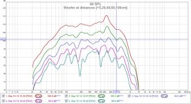
Addressing the 630Hz bump, damping using filling
There is a peak around 630Hz that I think is from a lambda/2 resonance between the bottom of the chamber and the woofer. ***** Ignore the data <60Hz, in the graph below it's from other neighborhood machines running. I really wanted to finish this.*****
This experiment is to add filling material (P=poly, Fg=fiberglass, #=cm) to the chamber to see it makes a difference. Previous measurements were made with 1/3 (8cm) of poly filling on the bottom. I have approx 23cm behind the woofer magnet to fill. I tried various combinations [8P, 8P+10Fg, 10Fg+8P, 15Fg+8P] to see what was most effective. The wave velocity will be highest in the middle of the chamber and that's where the filling is most effective. The fiberglass grain is always placed perpendicular to the wavefront movement.
With an open top woofer, (graph#1) the filling and the notch filter can eliminate the 630Hz peak. The 630Hz peak only reappears when the cone is added back as in graph#2. In all measurements, the electrical 630Hz notch filter was in place. I've concluded the problem is two fold, a chamber resonance as well as an interaction between the woofer and cone. At distance (graph#3) the peak's significance is greatly reduced so the solution's urgency is lower on my list for now.
My end solution was [15Fg+8P] completely filling the chamber. The loosest filling is poly and that was directly behind to woofer to allow it a little breathing room.
Attachments
Axisymmetric waveguides particularly round ones often have an on axis dip which is not there at off axis angles.
With your waveguide in free air did you measure at off axis angles to see if there was a difference.
I don't know if this would have an interaction with your cones but it could be worth looking at.
The junction between CD and waveguide is very important and even the CD not being perfectly centred due to the tolerance of the screw mount can make a difference. Plenty of information on that elsewhere.
Fibreglass seems to have helped. I found a layer of felt in front of the fibreglass was the best combination. Fibreglass and acrylic ended up being just too much. It's easier to see in an impedance graph as the peak starts to get skewed to one side when you have overstuffed the enclosure.
The sort of felt I used was automotive underlay and was pretty cheap to get about 10mm thick. Very much like a removalists blanket or felt carpet underlay. You might be able to grab an offcut from a carpet place, it tends to still be used in cold climates.
Axisymmetric waveguides particularly round ones often have an on axis dip which is not there at off axis angles.
With your waveguide in free air did you measure at off axis angles to see if there was a difference.
I don't know if this would have an interaction with your cones but it could be worth looking at.
The junction between CD and waveguide is very important and even the CD not being perfectly centred due to the tolerance of the screw mount can make a difference. Plenty of information on that elsewhere.
Good idea. I've never measured off axis or at distance to see how the CD+WG behaves. I'll post some measurements.
Fibreglass seems to have helped. I found a layer of felt in front of the fibreglass was the best combination. Fibreglass and acrylic ended up being just too much. It's easier to see in an impedance graph as the peak starts to get skewed to one side when you have overstuffed the enclosure.
The sort of felt I used was automotive underlay and was pretty cheap to get about 10mm thick. Very much like a removalists blanket or felt carpet underlay. You might be able to grab an offcut from a carpet place, it tends to still be used in cold climates.
I'm happy with the chamber fill and performance on its own. I think the interaction between the cone and woofer requires a different solution. Probably the cone shape.
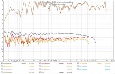
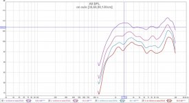
Fane CD130 plus Dayton 10" circular waveguide
My HF saddle shaped FR has been partially flattened using a notch filter@2.5KHz but still has a few issues. With the cone in place the performance is similar to the WG on its own, but I've only ever measured the CD+WG on axis. @fiuid had a good suggestion to characterize it more completely.
Graph#1 is off axis angular performance 30cm from the mouth center. The WG + CD + mounting frame + XO + 2.5Khz notch filter to reduce the first bump are included. The WG is pointed forward open space and 1m off the ground. There is a gradual loss of performance until about 75deg where it just collapses (several retries to confirm).
Graph#2 is performance vs distance to see it if it "evens" out. It doesn't.
I have tested without the mounting frame, and the 15KHz bump is still there (its not the reason). I've also used APO EQ to limit the signal output to 12KHz and used REW to test up to 20Khz to check if its a diffraction effect (its not the reason). IMO its an issue with the CD+WG operating at 15KHz.
I believe a simple RC filter just before 15KHz will flatten it to my liking")
My HF saddle shaped FR has been partially flattened using a notch filter@2.5KHz but still has a few issues. With the cone in place the performance is similar to the WG on its own, but I've only ever measured the CD+WG on axis. @fiuid had a good suggestion to characterize it more completely.
Graph#1 is off axis angular performance 30cm from the mouth center. The WG + CD + mounting frame + XO + 2.5Khz notch filter to reduce the first bump are included. The WG is pointed forward open space and 1m off the ground. There is a gradual loss of performance until about 75deg where it just collapses (several retries to confirm).
Graph#2 is performance vs distance to see it if it "evens" out. It doesn't.
I have tested without the mounting frame, and the 15KHz bump is still there (its not the reason). I've also used APO EQ to limit the signal output to 12KHz and used REW to test up to 20Khz to check if its a diffraction effect (its not the reason). IMO its an issue with the CD+WG operating at 15KHz.
I believe a simple RC filter just before 15KHz will flatten it to my liking
Attachments
Last edited:
Still have the same problem in HornResp or ABEC LEM. The parameters to model the CD are missing.
With Hornresp, if the driver parameter values are not known, simply set Eg = 0 so that the driver diaphragm is given a constant rms velocity of 10 cm/sec. This provides a reasonable indication of overall performance.
Agree as fluid said that post 188 impulse looks weird, could it be one driver has polarity reversed which could be checked looking into impulse or step response first curves in same post, would mean polarity should be same and then if there is time alignment difference that difference should be tweaked adjust relative distance on threaded rods.
With Hornresp, if the driver parameter values are not known, simply set Eg = 0 so that the driver diaphragm is given a constant rms velocity of 10 cm/sec. This provides a reasonable indication of overall performance.
Thanks David, that's a good tip that will allow me to experiment with profiles.
the more I read it the more I feel that the name of this thread should be "Cone Wars", cause it's more and more about fighting the problems created by cones.
Possibly
but despite the refinement issues they are doing what I want (more or less). Hopefully I won't end up falling on my own "cone". I might even try a sphere, it would be easy enough.Agree as fluid said that post 188 impulse looks weird, could it be one driver has polarity reversed which could be checked looking into impulse or step response first curves in same post, would mean polarity should be same and then if there is time alignment difference that difference should be tweaked adjust relative distance on threaded rods.
I actually checked this by reversing the CD polarity. The impulse was virtually the same. It looks like the impulse response of a sinc function.
What part is causing the "weird" alert. What should or not be there?
- Home
- Loudspeakers
- Multi-Way
- OmniDirectional - work in progress