Omni V5 - construction - mid disk cone base
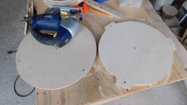
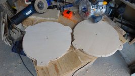
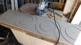
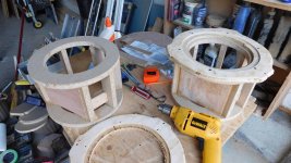
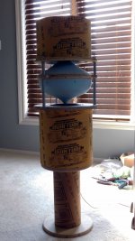
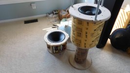
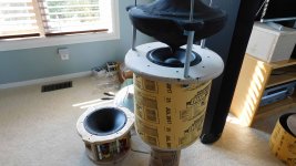
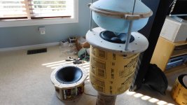
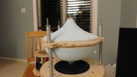
The middle disc needs to be smaller than the woofer baffle and smaller than the wave guide baffle. Its difficult to sand a foam core to a reliable fine tip, so I cut off the foam tips and replace them with a clay tips. Clay is easy to form and sand to a smooth finish and can be replaced easy.
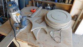
The polystyrene cones are mounted to the middle disk using screws. The sureply backing is glued to the foam and creates a rigid structure that takes screws. This way I can easily remove and replace a cone.
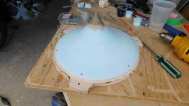
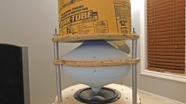
Just to make sure everything fits, I do a dry run assembly before building the cover for the tweeter compression driver. The HF cone tip can be viewed top down through the wave guide to make sure its centered.
The middle disc needs to be smaller than the woofer baffle and smaller than the wave guide baffle. Its difficult to sand a foam core to a reliable fine tip, so I cut off the foam tips and replace them with a clay tips. Clay is easy to form and sand to a smooth finish and can be replaced easy.
The polystyrene cones are mounted to the middle disk using screws. The sureply backing is glued to the foam and creates a rigid structure that takes screws. This way I can easily remove and replace a cone.
Just to make sure everything fits, I do a dry run assembly before building the cover for the tweeter compression driver. The HF cone tip can be viewed top down through the wave guide to make sure its centered.
Attachments
Member
Joined 2009
Paid Member
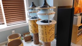
Actually, they are placed 1.3m from a wall front, which also the same distance the listening position is from the back wall. OmniDirectional - work in progress
It's an interesting idea to see what the sound field would be like from asymmetric placement. It would probably only have an effect at higher frequencies. It would be easy to check it using ABEC so you could see the field pattern, rather that building a model.
Might be easier to use something like an acoustic lense.
Hopefully ")
The reflections from the incident wave off the front wall and the back wall are approx the same time (and distance) only in opposite directions partially cancelling (null). This leave the incident wave and lateral wall reflections with minimal cross talk. It sounds a bit better in this position.
The reflections from the incident wave off the front wall and the back wall are approx the same time (and distance) only in opposite directions partially cancelling (null). This leave the incident wave and lateral wall reflections with minimal cross talk. It sounds a bit better in this position.
Omni V5 - construction - HF waveguide housing
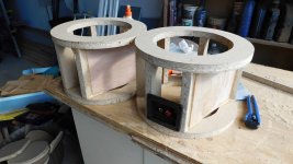
A bit of a delay, after getting the garage back from my offspring.
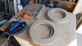
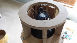
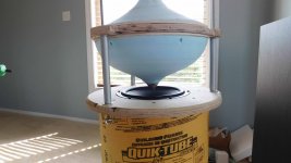
The compression driver and waveguide need a structure, and I wanted to move the electrical stuff up to the top where its easier for me to modify without disassembling the entire unit. Another wooden cylinder is constructed from rings and struts. This keeps it stiff, light and provides bays for the electrical stuff. The bay backplates are made from sureply and are glued in place.
A bit of a delay, after getting the garage back from my offspring.
The compression driver and waveguide need a structure, and I wanted to move the electrical stuff up to the top where its easier for me to modify without disassembling the entire unit. Another wooden cylinder is constructed from rings and struts. This keeps it stiff, light and provides bays for the electrical stuff. The bay backplates are made from sureply and are glued in place.
Attachments
Omni V5 - construction - electrical
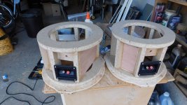
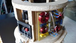
I moved all the electrical stuff up to the top for easy access.
One bay has the LR4 + Zobel comp, and another has the speaker terminals plus L-pad for HF attn. Everything is modular and connected using quick disconnects.
The quik tube slides over the entire top making a uniform exterior surface and a small semicircle at the back bottom allows wire exit.
Attachments
Woofer section tests
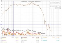
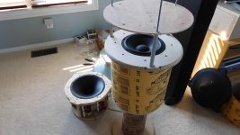
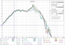
Compared to V4, the V5 cones and discs have changed dimensions and now have a 16L sealed chamber. I'll measure the response again to see what tuning is required. Only the woofer and XO are connected.
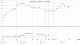
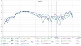
The V5 has a peak at 630Hz, from the chamber length behind the woofer. Graph#1 is the woofer off axis, no cones, at the disc edge 7 cm up (mid disc height). I've also suspected there may be interaction between the cone and the woofer setting up a resonance at this freq. So I check a few other cone shapes [none, flat disc, V4 LF + HF, plus V5 LF + HF] to see if I could reduce it. Turns out there is interaction and its centered around the 630Hz =(344/(2*0.27m) or 1/2 lambda as shown in graph#2. Different shapes have different issues and the final cone shape mimics the response of "no cone" as shown in graph#3. This sounds odd, but it seems to be the least "interference" and allows me to add the HF section above without creating more issues like a flat top above the woofer. In most cases the response below 430 ( 1/4 woofer diameter) is the same regardless of cone shape until the woofer starts getting directional at 1/4 lambda 344/(0.2m*4)= 430Hz
The final cone shape still allows some resonance, so a series RLC notch filter was added in parallel to the woofer to suppress it. There is still some residual bumpiness that will be EQ'd out later, or maybe with damping using different chamber fill. In either case I'm happy with it and HF testing is next.
Compared to V4, the V5 cones and discs have changed dimensions and now have a 16L sealed chamber. I'll measure the response again to see what tuning is required. Only the woofer and XO are connected.
The V5 has a peak at 630Hz, from the chamber length behind the woofer. Graph#1 is the woofer off axis, no cones, at the disc edge 7 cm up (mid disc height). I've also suspected there may be interaction between the cone and the woofer setting up a resonance at this freq. So I check a few other cone shapes [none, flat disc, V4 LF + HF, plus V5 LF + HF] to see if I could reduce it. Turns out there is interaction and its centered around the 630Hz =(344/(2*0.27m) or 1/2 lambda as shown in graph#2. Different shapes have different issues and the final cone shape mimics the response of "no cone" as shown in graph#3. This sounds odd, but it seems to be the least "interference" and allows me to add the HF section above without creating more issues like a flat top above the woofer. In most cases the response below 430 ( 1/4 woofer diameter) is the same regardless of cone shape until the woofer starts getting directional at 1/4 lambda 344/(0.2m*4)= 430Hz
The final cone shape still allows some resonance, so a series RLC notch filter was added in parallel to the woofer to suppress it. There is still some residual bumpiness that will be EQ'd out later, or maybe with damping using different chamber fill. In either case I'm happy with it and HF testing is next.
Attachments
-
 DSCN2077 reduced.jpg560.5 KB · Views: 158
 -
 woofer no cone off axis@disc edge.jpg116.2 KB · Views: 112
 -
 DSCN2078 reduced.jpg529.4 KB · Views: 122
 -
 DSCN2079 reduced.jpg525.2 KB · Views: 106
 -
 DSCN2081 reduced.jpg486.7 KB · Views: 97
 -
 woofer various cones @disc edge.jpg125.1 KB · Views: 113
 -
 DSCN2082 reduced.jpg399.8 KB · Views: 119
 -
 woofer final cone.jpg117 KB · Views: 131
Last edited:
If your speaker was active you could use EQ to get the final acoustical slope of the crossover to match more closely to the slope you are aiming for which would make the summation flatter.
Hard to do that in a passive as the EQ would be applied to both legs. Could be useful to check how close the passive components you used got to the slope you were after.
If you get to go active with your Pi project it might be more useful to you.
Hard to do that in a passive as the EQ would be applied to both legs. Could be useful to check how close the passive components you used got to the slope you were after.
If you get to go active with your Pi project it might be more useful to you.
I'm OK with the passive filter slopes and they're close enough to design intent. There is just a little more slope than planned, probably from the woofer fading.
An active system definitely has advantages and it would mesh well with the RPI project. That being said, I would still have all the physical issues to sort out which have been mostly separate from the XO and EQ.
An active system definitely has advantages and it would mesh well with the RPI project. That being said, I would still have all the physical issues to sort out which have been mostly separate from the XO and EQ.
HF section tests
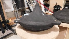
The cone is basically the same profile as the inside of the waveguide with extended slopes to the edge of the disc. I can replicate the approximate shape in polystyrene. Adjustments were made to the initial cone diameter (tip) and the slope contour.
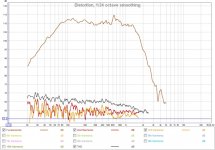
The baseline waveguide and compression driver, in open air (no cone) are shown in graph#1. Its not a very flat response and I'm not sure if its the WG or the CD or possibly interaction with the XO. I don't have other horns or compression drivers to compare to.
Various cone shapes with moderate different slopes and curvatures were tried to reproduce the baseline open air response at the disc edge with the cone in place. Graph#2 shows that below 5Khz the response is not that sensitive to the cone shape adjustments. Above 5Khz, small changes in the slope or the gap can make a significant difference. I think this will be an ABEC exercise eventually.
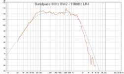
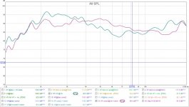
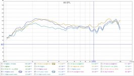
Even with the cone improvements there is still significant bump at 2.5KHz which is reduced using a series RLC notch filter. Graph#3 compares the V4 and V5 performance at 1m and its much flatter. Graph#4 compares the open air response to the V5 with notch filter at disc edge. We have the open air response at the disc edge.
The cone is basically the same profile as the inside of the waveguide with extended slopes to the edge of the disc. I can replicate the approximate shape in polystyrene. Adjustments were made to the initial cone diameter (tip) and the slope contour.
The baseline waveguide and compression driver, in open air (no cone) are shown in graph#1. Its not a very flat response and I'm not sure if its the WG or the CD or possibly interaction with the XO. I don't have other horns or compression drivers to compare to.
Various cone shapes with moderate different slopes and curvatures were tried to reproduce the baseline open air response at the disc edge with the cone in place. Graph#2 shows that below 5Khz the response is not that sensitive to the cone shape adjustments. Above 5Khz, small changes in the slope or the gap can make a significant difference. I think this will be an ABEC exercise eventually.
Even with the cone improvements there is still significant bump at 2.5KHz which is reduced using a series RLC notch filter. Graph#3 compares the V4 and V5 performance at 1m and its much flatter. Graph#4 compares the open air response to the V5 with notch filter at disc edge. We have the open air response at the disc edge.
Attachments
-
 DSCN2083 reduced.jpg441.8 KB · Views: 272
 -
 baseline waveguide + driver open.jpg74.1 KB · Views: 274
 -
 DSCN2089 reduced.jpg455 KB · Views: 269
 -
 compare various HF shapes.jpg96.9 KB · Views: 265
 -
 DSCN2088 reduced.jpg397.4 KB · Views: 144
 -
 compare flatness v4 to v5.jpg76.8 KB · Views: 126
 -
 compare open WG to final cone.jpg87.6 KB · Views: 84
Last edited:
Compared to V4, the V5 cones and discs have changed dimensions and now have a 16L sealed chamber. I'll measure the response again to see what tuning is required. Only the woofer and XO are connected.
The V5 has a peak at 630Hz, from the chamber length behind the woofer. Graph#1 is the woofer off axis, no cones, at the disc edge 7 cm up (mid disc height). I've also suspected there may be interaction between the cone and the woofer setting up a resonance at this freq. So I check a few other cone shapes [none, flat disc, V4 LF + HF, plus V5 LF + HF] to see if I could reduce it. Turns out there is interaction and its centered around the 630Hz =(344/(2*0.27m) or 1/2 lambda as shown in graph#2. Different shapes have different issues and the final cone shape mimics the response of "no cone" as shown in graph#3. This sounds odd, but it seems to be the least "interference" and allows me to add the HF section above without creating more issues like a flat top above the woofer. In most cases the response below 430 ( 1/4 woofer diameter) is the same regardless of cone shape until the woofer starts getting directional at 1/4 lambda 344/(0.2m*4)= 430Hz
The final cone shape still allows some resonance, so a series RLC notch filter was added in parallel to the woofer to suppress it. There is still some residual bumpiness that will be EQ'd out later, or maybe with damping using different chamber fill. In either case I'm happy with it and HF testing is next.
It looks You have a lot of problems with those cones - so why such a cone at all?
I understand that You'd like to put the tweeter above the woofer but in that case why not just aim a compact neodymium tweeter up and the "cone" required in such configuration (to mount the tweeter in) would be much smaller and creating less problems. Actually it could be in a shape and material minimizing reflections which are utterly undesirable.
Perhaps it wouldn't look so cool like a Duevel clone but definitely less problems.
Up to 10K the response is just like most waveguides/horns you get a greater efficiency as you go down in frequency until the waveguide loses pattern control. The bump at 15K is not quite so normal but could well be breakup. Is it there in the manufacturers data?Its not a very flat response and I'm not sure if its the WG or the CD or possibly interaction with the XO. I don't have other horns or compression drivers to compare to.
The shape of the tip will be acting as a phase plug so different shapes there might be worth looking at.
- Home
- Loudspeakers
- Multi-Way
- OmniDirectional - work in progress