.....There is a lot of math that is being done to create the IR+SR from FR and I believe it is correct but I'm not sure how important it is. I can tweak the HF cone tip and get a change in the initial rising pulse and the IR + SR. It's still weird, but now I know where to look...
Hi Don if you feel for it simply ignore me
 but i would investigate further because think that math from those two programs tells the truth, and that is probably something about as soon as cone is added to WG some acoustic delay or canceling is happening to particular frq dependent areas transferring unit to be a non minimum phase device in time domain and only amplitude domain looks right as a minimum phase device.
 If this is right and lets say time alignment between tweeter and woofer is alright you won't get a more than 30dB deep notch say reverse polarity for tweeter as in first graphs below.
In your third attachment post 239 it could be interesting see absolute phase because down in legend it says +166º at 3,51kHz and compared my synthetic simulation it should rather be in area of +60º as in second graph below.
Attachments
Last edited:
Hi Don if you feel for it simply ignore me
If this is right and lets say time alignment between tweeter and woofer is alright you won't get a more than 30dB deep notch say reverse polarity for tweeter as in first graphs below.
All help is welcome and appreciated. I would not have gotten this far without it
I agree, the defect is there, as both ARTA and REW have both come to the same conclusion via different methods. Even if I correct the rising edge, I still have the undershoot, which is causing the glitch in the step response. The CD+WG on there own have almost symmetric +ve and -ve pulses. I have been busy checking into this, as I'm not ready to ignore it l
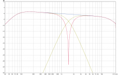
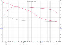
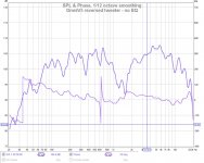
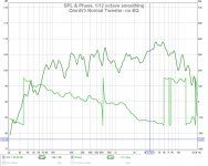
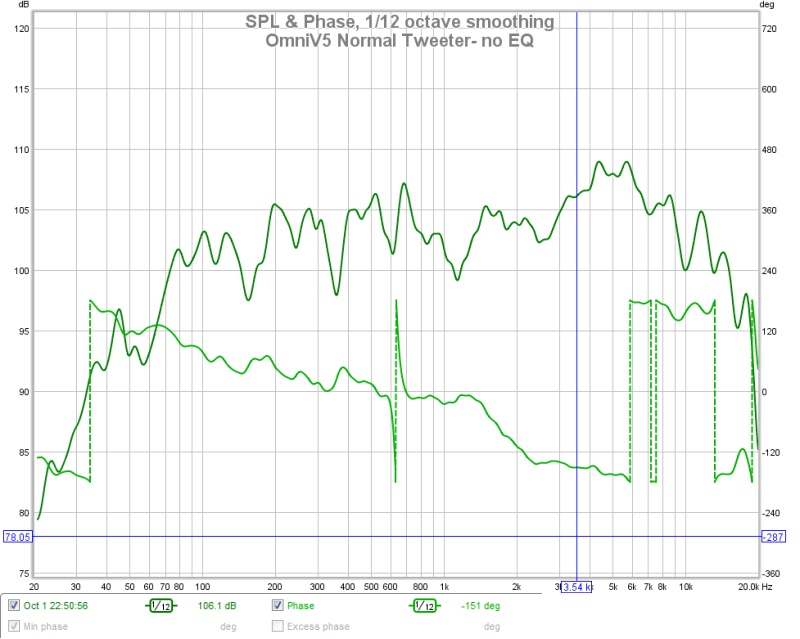
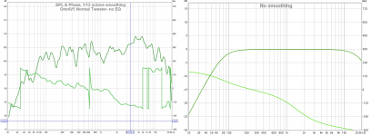
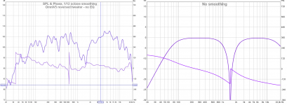
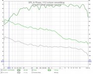
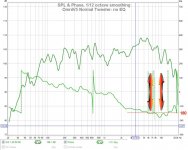
Graph#1 is for a reversed tweeter, no EQ, so you can see the dip and the phase shift up (direction change). The dip is less than 30db. A notch filter at 630Hz is causing a phase twist. Graph#2 is for the tweeter with correct polarity and no EQ and phase direction is the same.
In your third attachment post 239 it could be interesting see absolute phase because down in legend it says +166º at 3,51kHz and compared my synthetic simulation it should rather be in area of +60º as in second graph below.
The reverse tweeter looks like your graph#1, and the normal tweeter phase looks like your graph#2. Hopefully, I provided the graphs you were looking for.
Attachments
The reversed tweeter graph looks good from a phase perspective, have you tried to use that phasing for the tweeter and reversing the phase of the woofer to keep that cleaner phase for the tweeter but get the summation you want from the crossover?
I actually reverted to testing the woofer with a 1.5VDC battery to convince myself that the polarity was correct. It is correct.
Then in post#239, I tested the CD+WG on its own to confirm polarity. It is correct. When the HF cone is added it attenuates the initial +ve pulse, and I have been working (successfully) on improving that issue. I've even replaced the LR4 HF with a series cap to make sure its not something in the XO.
The problem (IMO) is the initial HF IR undershoot that is causing a glitch in the SR. I have been busy testing to see if I can find another HF driver that does not exhibit that wild undershoot (post coming soon). It's the HF IR undershoot that is ruining the SR.
what should the IR of an HF driver look like
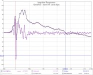
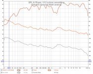
I have been trying to improve the initial HF rising edge from the HF cones. There have been many trials with the cone-waveguide gap, and various tips, and various tip-bugscreen gaps. I have one that is an improvement, and I think it will be better when I properly sand and finish it. Smoothness in this area seems to count. Graph#1 shows the new tips.
However, even if I restore the rising edge to be a perfect copy of the CD+WG, it will not be enough. The following HF undershoot will still cause a dip in the SR. This entire adventure (and the callus on my forehead ) is because of this undershoot. The question "is it only on this CD+WG combination?". Time to test a few other units.
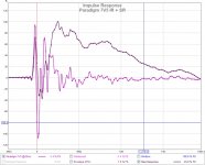
The Paradigm 7V5 uses a titanium done tweeter and shows a similar undershoot from the HF driver. Graph#2.
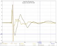
The Dayton DC28F is a silk dome tweeter left over from earlier trials also shows undershoot and it effects the SR. Graph#3, but limited bandwidth (2KHz-20KHz)to protect the tweeter.
I should add that I also tried the Fane CD130 + WG, and the Dayton DC28F with just a series capacitor (4.7uF) to convince myself it was not the LR4 XO. Nearly the same result, lots of undershoot and it shows up in the SR.
.
I have been trying to improve the initial HF rising edge from the HF cones. There have been many trials with the cone-waveguide gap, and various tips, and various tip-bugscreen gaps. I have one that is an improvement, and I think it will be better when I properly sand and finish it. Smoothness in this area seems to count. Graph#1 shows the new tips.
However, even if I restore the rising edge to be a perfect copy of the CD+WG, it will not be enough. The following HF undershoot will still cause a dip in the SR. This entire adventure (and the callus on my forehead
) is because of this undershoot. The question "is it only on this CD+WG combination?". Time to test a few other units.The Paradigm 7V5 uses a titanium done tweeter and shows a similar undershoot from the HF driver. Graph#2.
The Dayton DC28F is a silk dome tweeter left over from earlier trials also shows undershoot and it effects the SR. Graph#3, but limited bandwidth (2KHz-20KHz)to protect the tweeter.
I should add that I also tried the Fane CD130 + WG, and the Dayton DC28F with just a series capacitor (4.7uF) to convince myself it was not the LR4 XO. Nearly the same result, lots of undershoot and it shows up in the SR.
.
Attachments
My comment wasn't based on the absolute polarity of the drivers in reality it doesn't matter. But in the graphs the reversed tweeter looks much better, it looks like the cone and CD combined work better that way. I would be tempted to keep the tweeter like that and reverse the woofer to get your crossover to sum. But perhaps then the woofer will look worse, it would be interesting to see and easy to do by switching the wires around.
Anytime you have drivers in opposite polarity combined it is likely that the step response will not look the best. Whilst it is good to have a nice one I don't think it is the most important factor to consider, although it is quite handy for helping to work out issues as they become visible.
The response of the Dayton silk dome tweeter is odd, it does not look like it should to be more negative than positive.
High frequency peaks and ringing in the driver can cause some odd looking impulses, being dominated by high frequencies.
Some of those things are discussed with some pictures here
Pawel/Ensemble PA-1 & Reference loudspeakers Measurements | Stereophile.com
Stereophile is actually a pretty good source of information on impulse responses.
Thanks support graphs, but don't agree fluid that reversed tweeter look good in that it should explode a wrap of 180º at XO point leading to more than -30dB clean acoustic dip as we often see at T. Graversen website when he over there use passive XO 2nd or 4th order slopes, in perfect synthetic simulated domain such a reversed polarity lead to a clean dip more than -50dB. Wonder if tweeter motor is too weak to push VHF when loaded with that cone so that amplitude gets thru on graphs but delayed in time so that we miss XO region to be in phase which will lead to variable tilted lobes as phase varies between tweeter and woofer.
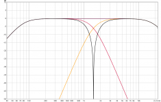
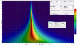
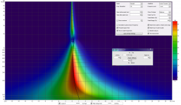
REW was updated yesterday (V5,19Beta7) and got new view settings, below wavelets including settings is simulation for BW2 80Hz - BW2 18kHz domain plus a 4th order LR XO point at 1,5kHz, first is normal and second have tweeter reversed, wonder how real thing looks compared here, will imagine it rolls like a bow to the right in tweeter domain area : )
REW was updated yesterday (V5,19Beta7) and got new view settings, below wavelets including settings is simulation for BW2 80Hz - BW2 18kHz domain plus a 4th order LR XO point at 1,5kHz, first is normal and second have tweeter reversed, wonder how real thing looks compared here, will imagine it rolls like a bow to the right in tweeter domain area : )
Attachments
I should have said "better"Thanks support graphs, but don't agree fluid that reversed tweeter look good in that it should explode a wrap of 180º at XO point leading to more than -30dB
Perhaps I didn't explain myself very well. I was not talking about the crossover region phase but the phase above 6K which is wrapped quite a number of times in the positive polarity (green) but not when reversed according to the previous graphs (Purple). That is what looks better to me
Are you talking about the dotted lines in graph #2?
That's not a phase wrap, it's just the phase overshooting 180 degree (with one or two degree's) and you can follow its path where the dotted lines lead you. It looks the same to me as the reversed tweeter, just 180 degree rotated. Unwrap phase command would get rid of the dotted lines.
That said, the hand-over in the crossover in graph #2 is way better but not ideal.
The IR as seen before with great STEP response should not be possible with a passive LR2 crossover, so that should immediately put up a red flag indicating something is not right.
Due to the waveguide/cone combo we have a gradual phase shift in the output. Of course that's going to show up in the IR/STEP. The plot in REW will be formed by assuming which one is the actual first arriving peak (it picks the peak with the highest energy). That will also "form" the phase curve.
Last edited:
Are you talking about the dotted lines in graph #2?
That's not a phase wrap, it's just the phase overshooting 180 degree (with one or two degree's) and you can follow its path where the dotted lines lead you. It looks the same to me as the reversed tweeter, just 180 degree rotated. Unwrap phase command would get rid of the dotted lines.
Yes I am and yes it is a termed a wrap, I do know that there is not a sudden phase flip there and it is due to the phase being "wrapped" in the display which is where the name comes from.
It is not 180 degrees but 360 degrees each time there is a dotted line. If the phase were to be unwrapped it looks like there would be a considerable deviation from the 360 synthetic version.
The fact that there are a few so close together could indicate that it is not just from the driver itself.
The Purple graph has a range of about 120 degrees all up. That looks better to me than the other but it is not textbook at all. Seems like I'm the only one who sees it like that.
Many thanks for all the ideas. This will be a long post to address all comments without having the discussion getting too fragmented. I will test all suggestions.
Yes, and it looks the same as a reversed tweeter. Its all relative, when one driver is reversed I get a phase increase at XO, and a FR hole.
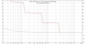
I'll repost the graphs with FDW, unwrapped phase and min phase. It seems there is some uncertainty as to what we are looking at.
Only, when I measure drivers independently, it appears that I have the correct polarity.
Everytime I see a common issue, I suspect a common denominator, but I have not found it yet I see all the HF drivers with nearly symmetric overshoot and undershoot.
An issue like that had occurred to me as well. You would need a few cycles to get the wavefront moving. I have another experiment to check this. I'll place the woofer and waveguide beside each other like a conventional speaker and see what I get.
The reposted graphs should clear this up. I agree, when the phase is a degree excess it wraps and looks funny, but I will unwrap it to make it clearer.
When I compare Omni to a conventional 2.5way I see the same IR + SR defect. It tells me there is something in common here.
I'll check this by forming a makeshift conventional speaker without the cones.
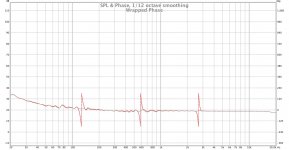
The reposted graphs below have FDW8 added (to reduce the effect of reflections), the phase unwrapped, and min phase generated. The 630Hz phase glitch is gone now. Its possible it was from a reflection, but I also have a resonance between the chamber and woofer cone at 630Hz.
... have you tried to use that phasing for the tweeter and reversing the phase of the woofer
Yes, and it looks the same as a reversed tweeter. Its all relative, when one driver is reversed I get a phase increase at XO, and a FR hole.
..... the graphs the reversed tweeter looks much better, it looks like the cone and CD combined work better that way.
I'll repost the graphs with FDW, unwrapped phase and min phase. It seems there is some uncertainty as to what we are looking at.
Anytime you have drivers in opposite polarity combined it is likely that the step response will not look the best. Whilst it is good to have a nice one I don't think it is the most important factor to consider, although it is quite handy for helping to work out issues as they become visible.
Only, when I measure drivers independently, it appears that I have the correct polarity.
The response of the Dayton silk dome tweeter is odd, it does not look like it should to be more negative than positive.
Everytime I see a common issue, I suspect a common denominator, but I have not found it yet
I see all the HF drivers with nearly symmetric overshoot and undershoot..... Wonder if tweeter motor is too weak to push VHF when loaded with that cone so that amplitude gets thru on graphs but delayed in time so that we miss XO region to be in phase which will lead to variable tilted lobes as phase varies between tweeter and woofer.
An issue like that had occurred to me as well. You would need a few cycles to get the wavefront moving. I have another experiment to check this. I'll place the woofer and waveguide beside each other like a conventional speaker and see what I get.
Are you talking about the dotted lines in graph #2?
That's not a phase wrap, it's just the phase overshooting 180 degree (with one or two degree's) and you can follow its path where the dotted lines lead you. It looks the same to me as the reversed tweeter, just 180 degree rotated. Unwrap phase command would get rid of the dotted lines.
That said, the hand-over in the crossover in graph #2 is way better but not ideal.
The reposted graphs should clear this up. I agree, when the phase is a degree excess it wraps and looks funny, but I will unwrap it to make it clearer.
The IR as seen before with great STEP response should not be possible with a passive LR2 crossover, so that should immediately put up a red flag indicating something is not right.
Due to the waveguide/cone combo we have a gradual phase shift in the output. Of course that's going to show up in the IR/STEP. The plot in REW will be formed by assuming which one is the actual first arriving peak (it picks the peak with the highest energy). That will also "form" the phase curve.
When I compare Omni to a conventional 2.5way I see the same IR + SR defect. It tells me there is something in common here.
Here is post 242 graphs verse simulation, its like tweeter motor loose power to load waves in time domain as frq goes up, at XO point take over its probably okay but loose about 180º at upper frq compared to simulation.
I'll check this by forming a makeshift conventional speaker without the cones.
Room modes and reflections are causing those phase flips and wraps. Measurements seem to have long IR gating.620Hz is propably a wall or ceiling.
The reposted graphs below have FDW8 added (to reduce the effect of reflections), the phase unwrapped, and min phase generated. The 630Hz phase glitch is gone now. Its possible it was from a reflection, but I also have a resonance between the chamber and woofer cone at 630Hz.
Attachments
Last edited:
Yes I am and yes it is a termed a wrap, I do know that there is not a sudden phase flip there and it is due to the phase being "wrapped" in the display which is where the name comes from.
It is not 180 degrees but 360 degrees each time there is a dotted line. If the phase were to be unwrapped it looks like there would be a considerable deviation from the 360 synthetic version.
Let's see if this helps. It really isn't a 360 degree wrap, here is the original phase plot where I moved the section between the dotted lines back where they "should" be.
See how this happens where phase is only slightly crossing the 180 degree line? The one at ~600 Hz really is a phase anomaly/deviation due to reflection or resonance. But in this case (between 5.5 and 14 kHz) it's certainly not anything to worry about. In fact, if we use the "invert impulse" on the impulse tab it will no longer have to show the dotted lines (at that point) to help you see it's continuation. That will move the phase part of the tweeter towards the zero line and dotted lines will appear whenever the + or - 180 degree is passed elsewhere. Unwrap phase would show something similar to what I have done here. The only function of the dotted lines is to move your eyes to the part that belongs to it. In itself the dotted line isn't an indication of a 360 degree wrap as shown here.
I've seen more people get confused with these type of graphs so I thought a little explanation might help more people. For anyone interested, force it in one of your own graphs by inverting the impulse to see what happens. It will move the graph from the "0" position to "180" and is bound to get it just outside to create such a double pair of dotted lines. Applying "Unwrap phase" might help clear things up too.
So there isn't a strong difference between the inverted tweeter graph and the non inverted graph in phase, except how they hand off to the woofer.
Hope this clears up what I was getting at.
Attachments
Last edited:
I know that the phase does not automatically jump 360 degrees just because there is a dotted line, it is the program constraining the phase to fit within limits.It really isn't a 360 degree wrap, here is the original phase plot where I moved the section between the dotted lines back where they "should" be.
The picture you posted does show that quite well as in this case the response goes back and forth across -180 causing the wrapping. It looks worse than it is. Just unwrapping the phase on that measurement without FDW would have shown it.
The one with more of a z shape does ramp here is a good example of that wrapped and unwrapped. As you say due to reflection.
Attachments
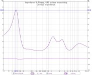
OmniV5 Impedance
I finally had a moment to build a fixture to use the REW's impedance measurement.
The fixture uses the PC sound card's headphone output, and line input. I added a switch for calibration. Another tool I wish I had made earlier.
The design goal (spice sim'd) was to have a 6 ohm lower limit to make it easy for my amp to drive.
Attachments
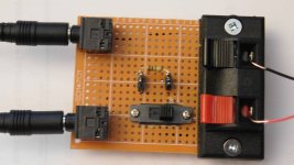
Great looking tool and diy work there.
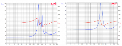
Could be wrong but isn't it strange phase is nearly flat : ) also maybe missing the usual by inductance rising impedance up at VHF but that could maybe be what omni cone is responsible.
As comparison first below is 2426H onto 2370a horn and second is 1 inch dome tweeter, btw had we been closer you had been very welcome borrow those 2426H for Omni build trials.
Attachments
I added the unwrapped phase versions to post #253 so we could avoid this debate.
I added it just because of lines like these:
Room modes and reflections are causing those phase flips and wraps. Measurements seem to have long IR gating.620Hz is probably a wall or ceiling.
It is not 180 degrees but 360 degrees each time there is a dotted line. If the phase were to be unwrapped it looks like there would be a considerable deviation from the 360 synthetic version.
We have more people reading along, I've seen it before that some people get thrown, usually just because a measurement is inverted and these dotted lines show up. All I wanted to show is that it's no big deal in a case like this for the area between 5.5 and 14 kHz. Removed the part where who said what in these quotes as I do not assume they didn't know what was happening. It's better to be clear about these things for all those that read along trying to learn from it. That's all. The example Fluid gave above should help people recognize a troubling phase wrap (caused by reflection) from a minor deviation due to phase barely crossing the 180 degree line. It should make them look at gating and the IR itself to see if they can find the cause of such a wrap.
The thing I'm still wondering about looking at that measurement is the slight hole it (still) has at the crossover. It looks like the tweeter is early. The shape of the FR does follow the phase. If we were to EQ the FR flat, and delay the tweeter a tiny bit it should all start to look better.
If you'd open that measurement in the new REW, make a spectrogram like BYRTT did a few posts ago one should see the wiggle in the timing.
Last edited:
- Home
- Loudspeakers
- Multi-Way
- OmniDirectional - work in progress