...I have another experiment to check this. I'll place the woofer and waveguide beside each other like a conventional speaker and see what I get...
Great idea and would be very interesting to see if tweeter start behaves as normal minimum phase device without use of Omni cone, would be good when times comes that you show graph not only for summing but also each individual band pass and tick on both absolute and minimum phase in non wrapped view mode
") .
.Great looking tool and diy work there.
Could be wrong but isn't it strange phase is nearly flat : ) also maybe missing the usual by inductance rising impedance up at VHF but that could maybe be what omni cone is responsible.
Yes, I caught the flat phase as well. It's very suspect. I'm checking into it.
As comparison first below is 2426H onto 2370a horn and second is 1 inch dome tweeter, btw had we been closer you had been very welcome borrow those 2426H for Omni build trials.
A very generous offer, but even if I were closer, I would not risk other's equipment on my experiment.
They are a much higher quality ($$$) than what I'm using.OmniV5 deconstructed, no cones
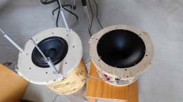
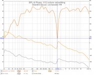
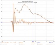
This is an attempt to see if the cones are causing the weird impulse. The speaker was disassembled, cones removed, and the driver baffles placed at approx the same height to resemble a conventional speaker (pic#1) lying on its back.
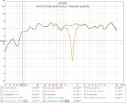
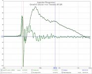
The graphs are very similar to the responses seen with the cones. The conclusion should be that cones are not causing the effect. The glitch in the step SR still appears to be caused by HF undershoot. I should note that I placed the mic over the HF WG (50cm) in these measurements. The further I mic towards the woofer, the more off axis the WG is and the less pronounced the effect is.
This is an attempt to see if the cones are causing the weird impulse. The speaker was disassembled, cones removed, and the driver baffles placed at approx the same height to resemble a conventional speaker (pic#1) lying on its back.
The graphs are very similar to the responses seen with the cones. The conclusion should be that cones are not causing the effect. The glitch in the step SR still appears to be caused by HF undershoot. I should note that I placed the mic over the HF WG (50cm) in these measurements. The further I mic towards the woofer, the more off axis the WG is and the less pronounced the effect is.
Attachments
-
 DSCN2276 reduced.jpg474.5 KB · Views: 234
 -
 OmniV5 deconstructed tweeter polarity.jpg118.6 KB · Views: 225
 -
 OmniV5 decon +ved tweeter FR.jpg109.3 KB · Views: 201
 -
 OmniV5 Decon +ve tweeter IR SR.jpg95.3 KB · Views: 198
 -
 OmniV5 decon -ve tweeter FR.jpg111.8 KB · Views: 192
 -
 OmniV5 Decon -ve tweeter IR SR.jpg93.3 KB · Views: 75
Great effort Don, a little suggestion if I may,
can you lift the speakers off the floor by 3-6 inches.
From my experience, speakers will sound more
harmonious & bass will go deeper. Give it a try
& see if it work for you
Cheers
In the "deconstructed" test, the driver baffles are 71cm off the floor.
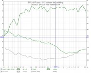
As an constructed Omni they sit on a 37cm stand, putting the woofer baffle at 71cm off the floor, and the WG baffle at 95cm from the floor. The bass rolls off at 100Hz because its a sealed chamber and intended to work with a separate subwoofer XO 80Hz.
Last edited:
Hi Don difficult to explain this, if your game just give it
a try. How high will depend on room interaction but minimum
is 3 inches to hear any effect. My ML Odyssey is lifted 5.5 inches
off the floor. What we all are playing with is acoustic feedback
with room interactions so basically anything is worth a try
Cheers
a try. How high will depend on room interaction but minimum
is 3 inches to hear any effect. My ML Odyssey is lifted 5.5 inches
off the floor. What we all are playing with is acoustic feedback
with room interactions so basically anything is worth a try
Cheers
This is an attempt to see if the cones are causing the weird impulse...
Confused here
what happened to that normal looking IR/SR from post 228 with new UMIK-1 microphone into chain:Something must cause those weird timing issues in HF area, in problem always is HF area what about measure a simple tweeter and see if that also gives weird timing issues in HF area, as reference see below attachments which is full band-width raw 1 inch tweeter on cardboard baffle, note how absolute verse minimum phase is mostly in agreement and deviation out at stop-bands are caused mostly by excess phase from measurement chain.
Attachments
Last edited:
Confused here
The "normal" looking IR you referenced used the older HF cone tip that destroyed the rising pulse edge, leaving only the undershoot. When the tweeter was inverted it looked like only a rising edge with no undershoot. It was why the SR looked so good, but it was wrong (a pretty illusion).
That cone tip problem was fixed in post #239. The new cone tips explained in Post#239 produce the same IR and SR as the no cone IR + SR.
Something must cause those weird timing issues in HF area, in problem always is HF area what about measure a simple tweeter and see if that also gives weird timing issues in HF area, as reference see below attachments which is full band-width raw 1 inch tweeter on cardboard baffle, note how absolute verse minimum phase is mostly in agreement and deviation out at stop-bands are caused by excess phase from measurement chain.
I agree, the problem is in the HF area. I get large undershoots with all the HF drivers I test Post#245.
...I agree, the problem is in the HF area. I get large undershoots with all the HF drivers I test Post#245.
Good hint there because into that post is Dayton DC28F and it should be good example comparable to mine 25mm tweeter as below.
How about viewing "Impulse" tab does IR/SR graphs from that post change to better if in "Controls" commanded "Estimate IR Delay" ?
Think in that trouble shooting area is HF related try concentrate get that DC28F tweeter to start look normal with a attack side reaching 100% in positive direction, and a absolute verse minimum phase that start look coherent.
There must be something in chain that under sweep can't keep up to speed in HF area, can think of reasons as mitch match in sample rate convertion or special sound card effects as SRS etc that should be disabled somewhere in a control panel or MS sound settings.
Attachments
Good hint there because into that post is Dayton DC28F and it should be good example comparable to mine 25mm tweeter as below.
How about viewing "Impulse" tab does IR/SR graphs from that post change to better if in "Controls" commanded "Estimate IR Delay" ?
I already use this to align the IR to t=0.
Think in that trouble shooting area is HF related try concentrate get that DC28F tweeter to start look normal with a attack side reaching 100% in positive direction, and a absolute verse minimum phase that start look coherent.
Given that I see similar behaviour, and the common element is my amp. I'm going to try experiment with different amps and speakers.
There must be something in chain that under sweep can't keep up to speed in HF area, can think of reasons as mitch match in sample rate convertion or special sound card effects as SRS etc that should be disabled somewhere in a control panel or MS sound settings.
I have turned off all processing on the PC and the amp. Next experiment is a different system.
Ending IR and SR measurements (for now)
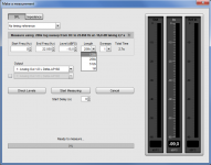
As a last is a series of IR + SR experiments, I have REW installed fresh on a laptop using the UMIK mic. All connections to the amps are analog. I have 3 different amps and 4 speakers to check.
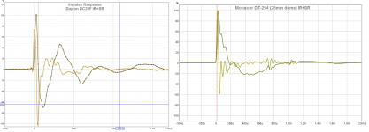
Graph#1 [OmniV5] has been measured with a both PC and laptop, and used both analog and digital inputs to RXV659 (all processing off). It looks the same in all measurements. This eliminated my PC and SPDIF as a potential cause. "it is,..what it is".
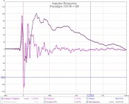
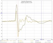
Graph#2 [Paradigm 7V5] is a 2.5 way BR connected to RXV659. It does not have a clean IR or SR and seems to have similar tweeter undershoot issues. One of its woofers is used like a mid-woofer and seems to cause another glitch in the SR.
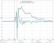
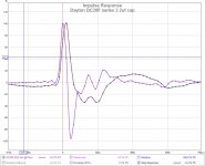
Graph#3 [Paradigm 11SEmk1] is a 3 way BR connected to a STR-DE305. It has an unattractive (being kind here) IR and SR. You can tell the tweeter is reversed in this speaker (2nd or 3rd order XO?). The midrange also looks like its reversed (or 2nd or 3nd order XO?). I've never taken it apart to check the XO, so its speculation.
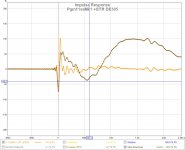
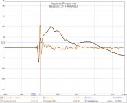
Graph#4 [Mission731] is a 2 way, damaged + repaired (tweeters) speaker connected to a AX900U. Also uses a 2nd order XO and the tweeter is reversed. (confirmed when repaired).
There is not much I can say about these IR and SR curves, other than they indicate driver polarity. I don't think they are all "broken" just because none of them look ideal. I suspect something like Linkwitz's Cos modulated Sine burst may be a better indicator than IR + SR. In either case, this (IR+SR) will move to the back of my "to do" list until I come across something that convinces me otherwise.
Many thanks for the advice and suggestions @byrtt, @fluid, @juhazi, @wesayso
As a last is a series of IR + SR experiments, I have REW installed fresh on a laptop using the UMIK mic. All connections to the amps are analog. I have 3 different amps and 4 speakers to check.
Graph#1 [OmniV5] has been measured with a both PC and laptop, and used both analog and digital inputs to RXV659 (all processing off). It looks the same in all measurements. This eliminated my PC and SPDIF as a potential cause. "it is,..what it is".
Graph#2 [Paradigm 7V5] is a 2.5 way BR connected to RXV659. It does not have a clean IR or SR and seems to have similar tweeter undershoot issues. One of its woofers is used like a mid-woofer and seems to cause another glitch in the SR.
Graph#3 [Paradigm 11SEmk1] is a 3 way BR connected to a STR-DE305. It has an unattractive (being kind here) IR and SR. You can tell the tweeter is reversed in this speaker (2nd or 3rd order XO?). The midrange also looks like its reversed (or 2nd or 3nd order XO?). I've never taken it apart to check the XO, so its speculation.
Graph#4 [Mission731] is a 2 way, damaged + repaired (tweeters) speaker connected to a AX900U. Also uses a 2nd order XO and the tweeter is reversed. (confirmed when repaired).
There is not much I can say about these IR and SR curves, other than they indicate driver polarity. I don't think they are all "broken" just because none of them look ideal. I suspect something like Linkwitz's Cos modulated Sine burst may be a better indicator than IR + SR. In either case, this (IR+SR) will move to the back of my "to do" list until I come across something that convinces me otherwise.
Many thanks for the advice and suggestions @byrtt, @fluid, @juhazi, @wesayso
Attachments
Think they are all broken because even graph#4 that is a known 2nd order and its SR begins look better there is that overruling big fault it won't ever reach 100% in attach direction that it should.
For more test in this area down the road suggest use that Dayton DC28F direct wired without any XO because then we have a clean speedy limited pass band and don't have to guess about how IR/SR should have looked because of summing/alignment with other pass bands and complicated XO networks.
One thing is shure when this culprit is revealed i probably never forget what caused problem, and shift coffee cup to a cold beer
As a last is a series of IR + SR experiments, I have REW installed fresh on a laptop using the UMIK mic. All connections to the amps are analog. I have 3 different amps and 4 speakers to check.
______
There is not much I can say about these IR and SR curves, other than they indicate driver polarity. I don't think they are all "broken" just because none of them look ideal. I suspect something like Linkwitz's Cos modulated Sine burst may be a better indicator than IR + SR. In either case, this (IR+SR) will move to the back of my "to do" list until I come across something that convinces me otherwise.
Many thanks for the advice and suggestions @byrtt, @fluid, @juhazi, @wesayso
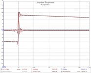
What does a loop back within REW of the audio chain including DAC look like? If that does not show a clean clear peak, nothing will. All it takes is a simple cable from DAC out to soundcard line in. Did we try that yet?
It probably is the easiest test of all. Yet it can be worth it to try. Testing all of the chain except speakers + amp.
Think they are all broken because even graph#4 that is a known 2nd order and its SR begins look better there is that overruling big fault it won't ever reach 100% in attach direction that it should.
Possibly, its all consumer grade product. BTW graph #4 sounds the worst and graph#3 sounds the best.

For more test in this area down the road suggest use that Dayton DC28F direct wired without any XO because then we have a clean speedy limited pass band and don't have to guess about how IR/SR should have looked because of summing/alignment with other pass bands and complicated XO networks.
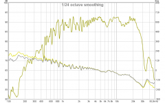
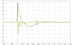
See attached graphs, there is still a significant undershoot regardless of XO and its what (IMO) is causing the SR glitch.
One thing is shure when this culprit is revealed i probably never forget what caused problem, and shift coffee cup to a cold beer
Thats for sure. So I'm having a nice glass of Cabernet now
Attachments
Not so optimistic about it because if remember right ARTA showed same behavour, but had you tried out from short to long length for sweep 128/256/512/1024 ?
Just tried min to max. Same results.
What does a loop back within REW of the audio chain including DAC look like? If that does not show a clean clear peak, nothing will. All it takes is a simple cable from DAC out to soundcard line in. Did we try that yet?
It probably is the easiest test of all. Yet it can be worth it to try. Testing all of the chain except speakers + amp.
I can see it being useful in determining if the output chain has a problem. I could run the Amp Lineout to the PC Line In.
Except I see the exact same problem when I use a laptop or the PC and either analog electret mic or UMIK.
Chain#1 out : PC soundcard -> SPDIF -> RXV659 (DACS)
Chain#2a in : UMIK -> USB -> PC
Chain#2b in : electret mic -> mic input -> PC soundcard
Chain#3 out : laptop headphone -> analog -> RX659 (analog)
Chain#4 in : UMIK -> USB -> laptop
Are they both running the same O.S.? We can assume it works like advertised, however it's a pretty simple test to run and be sure .
I even test my entire chain (which includes all kinds of DSP tricks) just to be sure.
Graph 3 doesn't look that bad to me. With a reversed tweeter and positive woofer it's a lot like I would expect. Remember, the IR is only a "rendered" shape of a lot more info. Don't take it too literary without seeing the other graphs that belong to it (or better said, are based on the same info).
The best or at least most clean IR I've ever seen from a LR2 speaker design was from jim1961. Nothing digital or with DSP, all natural and measured at the listening spot. But what a listening spot that is! This IR, combined with all other data he showed can tell us something about what he achieved. An IR plot by itself should never be judged without seeing the other graphs that make up it's story. You can even filter the IR on the Filtered IR tab to see what is going on. Look at wave shapes as filtered with 1/3 octave and compare it to a Dirac pulse. Or better yet a synthetic ideal of the crossover used, including it's band pass behaviour. That stuff shows you way more than the IR as plotted here. Look at it's (early) waterfall plot, investigate the measurement.
There is much more to it than the hunt for pretty graphs. It tells us what happens within that wave front.
.I even test my entire chain (which includes all kinds of DSP tricks) just to be sure.
Graph 3 doesn't look that bad to me. With a reversed tweeter and positive woofer it's a lot like I would expect. Remember, the IR is only a "rendered" shape of a lot more info. Don't take it too literary without seeing the other graphs that belong to it (or better said, are based on the same info).
The best or at least most clean IR I've ever seen from a LR2 speaker design was from jim1961. Nothing digital or with DSP, all natural and measured at the listening spot. But what a listening spot that is! This IR, combined with all other data he showed can tell us something about what he achieved. An IR plot by itself should never be judged without seeing the other graphs that make up it's story. You can even filter the IR on the Filtered IR tab to see what is going on. Look at wave shapes as filtered with 1/3 octave and compare it to a Dirac pulse. Or better yet a synthetic ideal of the crossover used, including it's band pass behaviour. That stuff shows you way more than the IR as plotted here. Look at it's (early) waterfall plot, investigate the measurement.
There is much more to it than the hunt for pretty graphs. It tells us what happens within that wave front.
Last edited:
Are they both running the same O.S.? We can assume it works like advertised, however it's a pretty simple test to run and be sure
I even test my entire chain (which includes all kinds of DSP tricks) just to be sure.
When I use REW impedance calibration measurement it uses cable line loop back and looks fine. Calibration=1.0000
When I use the REW SPL measurement, and cable line loop back, the variation is <0.2db pk-pk [20Hz-20KHz].
I think the PC sound card is OK. A good check though.
The PC (Win7) and the laptop (Vista) both run the same version of REW and show the same results. Both REW and ARTA also show the same result via 2 different methods.
Attachments
Last edited:
- Home
- Loudspeakers
- Multi-Way
- OmniDirectional - work in progress