Hello Steve
Nice work.
At this point, I am the student, and you are the teacher.
With regards to your second picture, phase.
Am I safe in making the following observation and statement; the woofer has its phase shift at approximately 2200Hz. The tweeter has its phase shift at approximately 1500Hz. Is it theoretically ideal to have the two lines (shifts) at the same frequency?
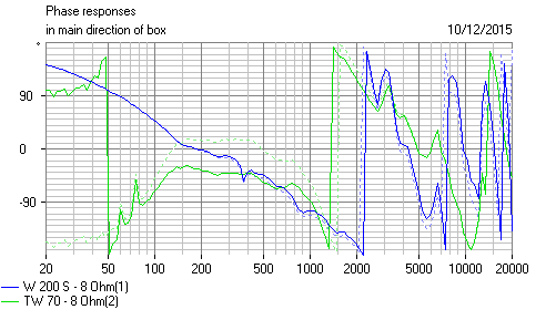
Way I'd look at it, is phase matters from 1.5kHz to 5kHz here, the overlap.
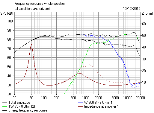
1.5KHz on the tweeter is the Fs resonance, hence the peak which you can equalise out with an LCR. 3kHz (5cm for half wavelength in air) on the woofer is a severe cone resonance. Not much you can do about that. It's just what an 8" speaker does due to the distance from voicecoil to the edge being about 5 cm. In practice it's usually quite benign in sound. It's the one centred at 6kHz you hear more IMO.
Phase is very revealing of resonances and stored energy even if frequency response looks flat. An S shaped kink usually.
There is a school of thought that phase should be exactly aligned on the two drivers, but this creates a hole in the power response with LR2 and LR4 above and below axis, which you can hear. You get what you get with phase, but I certainly don't mind 90 degree error at crossover going to no error at high frequency. It fills the hole in the power response and is known as BW3. Below.
Attachments

Where the lines "shift" is when the phase goes beyond the scale. Read the graph for the woofer @200=0 @3500=-360 @5000=-540.
What you want is minimal phase difference where two drivers responses overlap. The optimizer in Boxsim will do this for you. Set the positions of the drivers and it will optimise the filter components for FR and PR. It would have been nice if the optimizer would give you more control over preferences and could also optimise the drivers positions. You could then design the optimal electric filter and use the optimizer for driver positions only.
What you want is minimal phase difference where two drivers responses overlap. The optimizer in Boxsim will do this for you. Set the positions of the drivers and it will optimise the filter components for FR and PR. It would have been nice if the optimizer would give you more control over preferences and could also optimise the drivers positions. You could then design the optimal electric filter and use the optimizer for driver positions only.
Thank you Mark
I'm starting to understand.
If we look at our FR curve, we cross around 3500Hz.
If we look at our Phase graph, the two drivers are at the same point at 3500Hz.
Correct?
I'm starting to understand.
If we look at our FR curve, we cross around 3500Hz.
If we look at our Phase graph, the two drivers are at the same point at 3500Hz.
Correct?
Yes, but that is only looking at one frequency. 1500Hz to 3500Hz the tweeter/woofer still has a lot of output. What is the phase over these frequencies?
Hmmmm!
The phase is close, but not identical.
As Steve suggested, there may be advantages for the amplifier with 'not perfect'?.
The phase is close, but not identical.
As Steve suggested, there may be advantages for the amplifier with 'not perfect'?.
We have the original Accuton C50, and the new C51. Since the old is now discontinued, this was a simple look see.
The new Accuton C51 is housed in a solid case, no taking this one apart.
The C50 was a different animal.
Those tiny wires are likely 30awg. I have 28awg in my laboratory, and the Accutons are thinner.
No skin effect happening here.
The new Accuton C51 is housed in a solid case, no taking this one apart.
The C50 was a different animal.
Those tiny wires are likely 30awg. I have 28awg in my laboratory, and the Accutons are thinner.
No skin effect happening here.
Attachments


System7, your sim appears wrong- a parallel 8 ohm resistor with a parallel 2 way is not going to produce what appears to be a nominal 8 ohm impedance.
- Status
- Not open for further replies.
- Home
- Loudspeakers
- Multi-Way
- 4-Way Series Crossover. Accuton and Acoustic Elegance Drivers