Good morning Gentlemen
AllenB, I wasn't aware that an impedance peak means less energy is needed, thank you.
Steve, consider my question in post 116 ducked.
Your comment about driver selection mirrors my belief.
Let me know if my thinking is correct;
- capacitors affect the sound
- resistors affect the sound
- any time you can omit one or the other, the purer the sound.
I choose my drivers thusly
- the tweeter and midrange should be close in sensitivity. If anything, the tweeter can be 1 -2 dB BELOW the midrange.
- the midwoofer and woofer should be a minimum of 3dB higher in sensitivity. This compared to the tweeter and midrange. We know we'll lose 3dB from baffle loss'.
If the above parameters are met, no resistors will be needed. One of two necessary evils gone.
For our baffle loss, I build the cabinet first. In my case I have an 8.5" wide baffle.
If my thinking is correct, this equates to a wavelength of 1588Hz. Half this is 794Hz. May I assume my baffle step starts at 794, and rises to 1588. This would make my ideal theoretical crossover point 794Hz.
I have a 1" radius roundover starting ~1/8" away from the edge of the driver. If my thinking is correct, this will slightly reduce my baffle width, and raise the baffle step frequency?
May I call this a 'cabinet BSC'? or am I oversimplifying this and missing the point completely?
This is probably over-thinking it as the roundover has a more significant effect at much higher frequencies. You can take an 'average', say 0.7 of the roundover but by and large the difference is insignificant at the 'baffle step'.I have a 1" radius roundover starting ~1/8" away from the edge of the driver. If my thinking is correct, this will slightly reduce my baffle width, and raise the baffle step frequency?
There is no 'ideal' way to compensate the baffle step, only steps to either avoid it or make its effect inaudible.May I assume my baffle step starts at 794, and rises to 1588. This would make my ideal theoretical crossover point 794Hz.
John DeVore has his pet theory that his crossovers shouldn't have any resistors at all. He can of course custom design his driver's loudness. I have to admit I always find loudness adjustment with resistors robs the tweeter of liveliness.
Marco-Gea would win approval here from John: http://www.diyaudio.com/forums/multi-way/147632-classic-monitor-designs-25.html#post4428857
Joachim Gerhard is very expert in room and wall gain and the Allison effect and bafflestep, and designs his bass response accordingly. "One of the secrets, one of many..."
Thing is, simple filters are all very well, but they rely on incredibly well-behaved drivers. Expensive low-inductance damping rings, phase plugs, high Qms.
I also think bafflestep is a bit of a fudge. I prefer less, with smaller bass coils. The theory only even works if the speaker cabinet is in the middle of the room, and you still hear the room gain. Better to wall mount in some ways and avoid the issue. But then don't use a boomy high-inductance bass, comes with bafflestep built in. And FWIW, series filters don't seem to deal with bafflestep very well, you have fewer variables to play with, in what is essentially a fudge.
If you feel that less between the drivers and the amplifier is more, I wouldn't argue. But for all that, steep slopes sound less distorted. All the trade-offs!
On the subject of levels, a mid can be almost any loudness. Just adjust the filter! There are many ways to integrate 3 drivers to flatness.
Attachments
Last edited:
I choose my drivers thusly
You can also play with the internal resistance of the coils to avoid resistors.
In my test setup I use coils together with resistors, once I have found the correct values I order the coils with a resistance that match the resistance of coils and resistors in my test setup.
You can also play with the internal resistance of the coils to avoid resistors.
In my test setup I use coils together with resistors, once I have found the correct values I order the coils with a resistance that match the resistance of coils and resistors in my test setup.
Thank you danny
I forgot about that one.
There may be two sides to the resistance question. On one side there's whether a resistor can produce distortion, ie non-linear distortion, and yes one might. I find it more of an issue in amplifiers, not so much with speakers. Same goes for noise. But there's also the issue of adding resistance to a speaker circuit, or the side effects of doing so?
I hate "baffle step" terminologically. A step is usually very steep, but this phenomenom is not.
Baffle effect as sum of diffractions can not be neutralized by setting xo point somewhere, it still exists. We may discuss of how much of it is to be corrected. Usually this means remarkable loss of bass driver's nominal efficiency.
In rectangular boxes it is a bump by the way.
Baffle Step Compensation
An externally hosted image should be here but it was not working when we last tested it.
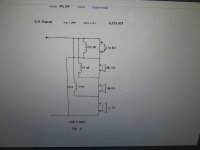
A quick recap.
This is for the Tweeter - Midrange x-over point. This is for our crossover topology.
The inductor value, which is typically 1/2 the value of what a parallel crossover would call for, is correct.
The capacitor, which is typically 2 times the value of what a parallel crossover would call for, is wrong. At least for our circuit.
For best distortion measurements, the multiplication factor from parallel to series should be 2.5 times.
We will skip over our Midrange - Mid Woofer measurements.
Our test box didn't have a chamfered inside edge.
Our test box didn't leave enough room between the magnet assembly of our TD6M and the inner box walls.
The new cabinet should be ready next week.
On to the Woofer - Mid Woofer measurements.
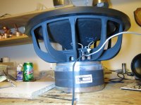
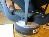
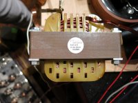
Let's look at our Acoustic Elegance TD15H+ driver.
Picture 1 & 2) Very solid build. 40+ Lbs. We are going to have a lot of fun removing, adding closed cell foam in places, replacing the driver back in box, measuring, removing, adding more stuff, replacing etc. You getta da picture. These observation will come in the next few days.
Picture 3) Series crossovers (it's said) benefit from large guage, low Rdc resistance inductors. For woofers, we have found 'cored' inductors sound best. Mundorf Zero Ohm Feron Cored, low Rdc (o.o4 Ohms) inductor. 5.6mH. Nice.
Our circuit has capacitor C3 (& C3B). This capacitor allows higher frequencies to bypass the woofer, and go on to the mid woofer.
We did a lot of waffling back and forth.
We tried a lot of values. These values ranged from 330uF down to 56uF. We'll show 4 of them.
The best of the bunch was 56uF. Let's show this first.
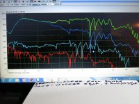
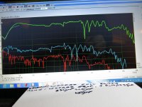
Picture 4) We start with 56uF (C3 and C3B), and add the TD15H+ full range. We like that this combination preserves the woofers output below ~100Hz.
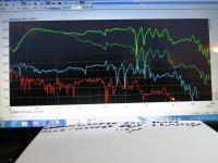
Picture 5) We add another 56uF in parallel. This gives us 112uF. We notice a slight drop in woofer output. 40Hz -80Hz. Where did this 'music' go?
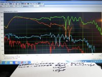
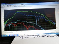
Picture 6) 150uF. Another small drop in output. Not good.
Picture 7) 330uF. We didn't even bother letting this continue. That bad.
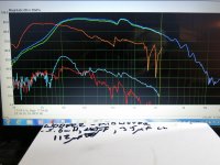
Picture 8) This is the mid woofer output. C3 is 56uF. We look at the distortion measurements, and put those in the back of our minds.
Picture 9) 112uF. Mid woofer measurement. D2 distortion has a bump around 100Hz.
I won't bother with the distortion measurements for the mid woofer for 150uF and 330uF. They where worse.
Conclusion; The mid woofers distortion is lowest when the capacitor C3 is optimized.
Until the new upper cabinet is finished, I won't worry about the mid woofer output from 500Hz to 1000Hz. This might be a box issue.
Our x-over point is ~110Hz.
Let's see what mh-audio.nl has to say?.
Let's see what the math says about parallel to series values. Will they still follow the 1/2 inductor and 2 times capacitor convention. Or will it show every series simulation used today, for a 3 or 4-ways, should be thrown in the garbage?.
I already know the answer.
I ask a question from before, are you willing to take the red pill and come down the rabbit hole?
Picture 1 & 2) Very solid build. 40+ Lbs. We are going to have a lot of fun removing, adding closed cell foam in places, replacing the driver back in box, measuring, removing, adding more stuff, replacing etc. You getta da picture. These observation will come in the next few days.
Picture 3) Series crossovers (it's said) benefit from large guage, low Rdc resistance inductors. For woofers, we have found 'cored' inductors sound best. Mundorf Zero Ohm Feron Cored, low Rdc (o.o4 Ohms) inductor. 5.6mH. Nice.
Our circuit has capacitor C3 (& C3B). This capacitor allows higher frequencies to bypass the woofer, and go on to the mid woofer.
We did a lot of waffling back and forth.
We tried a lot of values. These values ranged from 330uF down to 56uF. We'll show 4 of them.
The best of the bunch was 56uF. Let's show this first.
Picture 4) We start with 56uF (C3 and C3B), and add the TD15H+ full range. We like that this combination preserves the woofers output below ~100Hz.
Picture 5) We add another 56uF in parallel. This gives us 112uF. We notice a slight drop in woofer output. 40Hz -80Hz. Where did this 'music' go?
Picture 6) 150uF. Another small drop in output. Not good.
Picture 7) 330uF. We didn't even bother letting this continue. That bad.
Picture 8) This is the mid woofer output. C3 is 56uF. We look at the distortion measurements, and put those in the back of our minds.
Picture 9) 112uF. Mid woofer measurement. D2 distortion has a bump around 100Hz.
I won't bother with the distortion measurements for the mid woofer for 150uF and 330uF. They where worse.
Conclusion; The mid woofers distortion is lowest when the capacitor C3 is optimized.
Until the new upper cabinet is finished, I won't worry about the mid woofer output from 500Hz to 1000Hz. This might be a box issue.
Our x-over point is ~110Hz.
Let's see what mh-audio.nl has to say?.
Let's see what the math says about parallel to series values. Will they still follow the 1/2 inductor and 2 times capacitor convention. Or will it show every series simulation used today, for a 3 or 4-ways, should be thrown in the garbage?.
I already know the answer.
I ask a question from before, are you willing to take the red pill and come down the rabbit hole?
Attachments
-
 IMG_0954.jpg896.2 KB · Views: 253
 -
 IMG_0955.jpg805.4 KB · Views: 240
 -
 IMG_0965.jpg816.3 KB · Views: 239
 -
 IMG_0960.jpg906.4 KB · Views: 216
 -
 IMG_0961.jpg851.7 KB · Views: 210
 -
 IMG_0962.jpg908.6 KB · Views: 55
 -
 IMG_0963.jpg917.3 KB · Views: 61
 -
 IMG_0964.jpg865.4 KB · Views: 47
 -
 IMG_0957.jpg900 KB · Views: 57
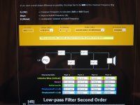
We go to MH-Audio.
We go to the section 'calculates 6dB, 12dB, 18dB slopes'.
We input; R = 8 Ohms (best guess average from manufacturers impedance plots)
We know; our measured x-over point is ~110Hz.
We look at LR (critical) values; L = 23.15mH. C = 90.4uF
If we divide this inductor value by 4, we get 5.78mH (close enough to our 5.6mH).
If we divide the parallel crossover capacitor value by 2, we get 45.2uF.
This might imply our measured best C3 of 56uF is still not the optimal.
I need to start measuring values below 56uF.
Let's look at this.
Let's concentrate on a 4-way. My topology.
We'll use what we've measured, and therefore what we've concluded, from what we've observed.
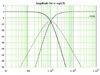
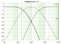
Tweeter - Midrange; 1/2 parallel inductor. 2.5 time parallel capacitor.
Woofer - Mid Woofer; 1/4 parallel inductor. 1/2 parallel capacitor.
It will freak me out if;
Once my new upper cabinet is finished,
and we do our measurements,
Mid Woofer - Midrange; 1/3 parallel inductor. 2 x's parallel capacitor.
Inductor; so far 1.2mH gives me the best response. Mh audio, for 8.5 Ohm average impedance at crossover, x-over ~800Hz, gives 3.38mH. 1/3 is 1.13mH (close enough for now)
Capacitor; tweeter is 2.5 times. This is 5/2. Woofer is 1/2. 5/2 minus 1/2 = 4/2.
This might imply our capacitor for the mid woofer - midrange should be 2 times the parallel calculation.
If it is higher, than we need to test out tweeter cap at 3 times parallel value, and not be content with 2.5 x's.
This is fun!!!!
We go to the section 'calculates 6dB, 12dB, 18dB slopes'.
We input; R = 8 Ohms (best guess average from manufacturers impedance plots)
We know; our measured x-over point is ~110Hz.
We look at LR (critical) values; L = 23.15mH. C = 90.4uF
If we divide this inductor value by 4, we get 5.78mH (close enough to our 5.6mH).
If we divide the parallel crossover capacitor value by 2, we get 45.2uF.
This might imply our measured best C3 of 56uF is still not the optimal.
I need to start measuring values below 56uF.
Let's look at this.
Let's concentrate on a 4-way. My topology.
We'll use what we've measured, and therefore what we've concluded, from what we've observed.
Tweeter - Midrange; 1/2 parallel inductor. 2.5 time parallel capacitor.
Woofer - Mid Woofer; 1/4 parallel inductor. 1/2 parallel capacitor.
It will freak me out if;
Once my new upper cabinet is finished,
and we do our measurements,
Mid Woofer - Midrange; 1/3 parallel inductor. 2 x's parallel capacitor.
Inductor; so far 1.2mH gives me the best response. Mh audio, for 8.5 Ohm average impedance at crossover, x-over ~800Hz, gives 3.38mH. 1/3 is 1.13mH (close enough for now)
Capacitor; tweeter is 2.5 times. This is 5/2. Woofer is 1/2. 5/2 minus 1/2 = 4/2.
This might imply our capacitor for the mid woofer - midrange should be 2 times the parallel calculation.
If it is higher, than we need to test out tweeter cap at 3 times parallel value, and not be content with 2.5 x's.
This is fun!!!!
Attachments
Last edited:
There's a lot of hype in that, don't you think?
One thing I might agree with him on is that it would be difficult to match drivers. How is this energy shared between unrelated impedances, how will it be the right amount between differing sensitivities, how much does the cone need to move for inverse doppler distortion and can I only listen at one volume setting?
One thing I might agree with him on is that it would be difficult to match drivers. How is this energy shared between unrelated impedances, how will it be the right amount between differing sensitivities, how much does the cone need to move for inverse doppler distortion and can I only listen at one volume setting?
Mr. Fkeller
Who's almost there?
I know I've only just scratched the surface.
My drivers where carefully chosen. Maybe I just got lucky.
What happens when we have a 16 Ohm woofer, 4 Ohm mid woofer, 8 Ohm midrange, and 6 Ohm tweeter.
The permutations are mind boggling.
Is there a relationship between L1, L2, and L3 for a 4-way?
Does my circuit fail miserably for a 3-way?
How would it look for a 5-way?
Is there a way of putting together a simulation program?
What if? What if? What if?
Mr. Fkeller. We've put the key in the ignition for our road trip.
Let's start by backing out of the driveway.
I did some more poking around and found this by Kimber on the subject of Dopler distortion.
Infinite. Have you tried simulating or are you trying to get started?The permutations are mind boggling.
- Status
- This old topic is closed. If you want to reopen this topic, contact a moderator using the "Report Post" button.
- Home
- Loudspeakers
- Multi-Way
- 4-Way Series Crossover. Accuton and Acoustic Elegance Drivers