@cookiemonster:
I had a look on your ABEC model and found out that there is an error in the QTWG Element in Subdomain 1. There is an small area which is not aligned correct. It is the small yellow area in the screenshot. The normal vector is pointing in wrong direction and thus the area is not correctly orientated. This will lead to an error in the simu.
Also the numbers of elemtens and DOFs is quite large, on my computer it would take 2-3hrs to solve the model. Symmetrie would be the way to go, but as I experienced ABEC has (or had?) its problems with symmetry and several (more than one) diaphs included.
For HF only simus I would highly recommend a quarter model, as the actual model has its practical limits to midrange only due to limiting computational time.
Best Regards
Andreas
Thanks Andreas,
I really appreciate that you dig in to find improvement potentials!
")
Several people have asked me why I don´t use symmetry. The reason is that if you want to split this model up into halves, you will split the Diaphragm representing the CD into two. So far so good, ABEC will handle it when you split an element like that. However, when you mirror the midrange holes, you are doubling the area driven by the LEM model. So if you have on the LEM side a 15mm exit for Driver 1, you will now get 2 15mm exits driven. When you want to investigate coupling, this won´t work. I had a symmetrical model that I sent to Jörg, and he recommended I make it the way it is now. However, when you include the midrange cavities and actual diapgragm into the BEM model, it is possible to mirror and still get the coupling required. I´m not terribly interested in the effect of the CD on the actual midrange diaphragm (imagine a passive radiator), since each element will be given their own amplifier channel and won´t really be influenced like that. But it´s important to see any resonances/reflections by the hole and cavity itself. Once you remove the need for electrical coupling, mirroring becomes possible. When Jörg enables damping on the Baffle element, I will include the woofer diapgragms and chambers into the BEM part of the model too, and then I see no reason to not use symmetry.
There are some bugs when it comes to orientation of normals in the ABEC display. I have reported one, and it was fixed, but I have later seen that there is at least one more. So when in doubt, try for a sanity check. The model as it is now, in my view, passes the sanity check.
For the bug you found: Yes, you are right, i was sloppy when excluding triangles. There are two that need to be removed to make this 100%, 170 and 114.
Elements "QTWG" // use with simplified v7 file
Subdomain=1; MeshFileAlias=HornMesh; Shift=-316.325mm,-316.325mm,-15mm
SwapNormals;
5000 Mesh Exclude 245...250, 8..15, 1...6, 170, 114
Of course, the best way to build this model would be to make a parametric set of nodes rather than importing a mesh file. If somebody volunteers to make an excel sheet or something that generates the triangles required for a QTWG I can include the logic in the Solving.txt. Number of triangles should be fixed, and inputs should be: Diameter of entry, Horizontal Angle and Vertical Angle.
re'
"For me front chamber volume and port length seem to be related. As you increase front chamber volume the port length needs to be increased to keep the output the same."
definitely true. try port lengths in the range of 1-4 cm that you might get when the sound has to funnel through a solid phase plug as well as the horn wall
I don't disagree with David either. You can model the height of the horn above the floor in AkaBak and Abec or get an approximate result with Jeff Bagby's Diffraction and Boundary Simulator spreadsheet. IMO, the worst case isn't not getting the predicted support, its getting a boundary null in the passband. which is why I would place my woofers outside the horn, D'Appolito style, were it not for how tall the speaker would then have to be.
which is why I would place my woofers outside the horn, D'Appolito style, were it not for how tall the speaker would then have to be.
I prefer woofers outside the horn as well. The horn can be constructed much smaller and more shallow.
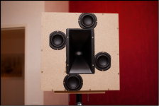
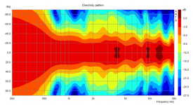
And a pseudo coax can yield to a directivity which fits perfect to a horn with narrow dispersion. I'm working on such a project at the moment. Still waiting for the right horn (40° x 40°) to arrive, but the prototype is promising. And its depth is only 20 cm.
Attachments
CookieMonster:
You had a long and productive day yesterday!
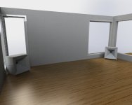
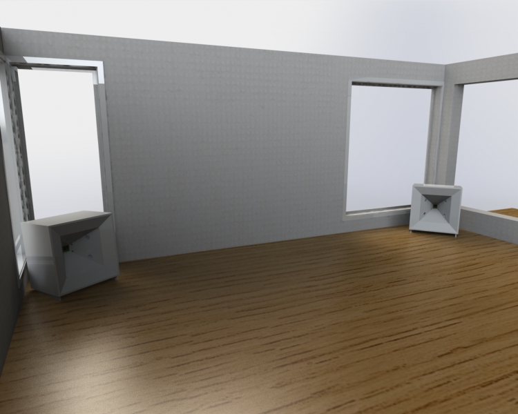
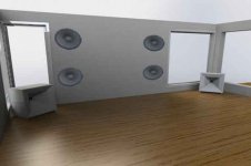
Is that what your finished design will look like? I had to look twice to see whether it was a photo or a rendition, but ultimately the emptiness of the room was the giveaway
My 90 degree corner horns tuck more tightly into the corner than yours but when I put them up on their Jubilee-like base bins, they are still hard to miss. Nothing one can do about the fact that size matters.
Are you going to extend your mesh to include the room? I guess that would/should be a separate simulation...nice that ABEC can do that too.
Jack
You had a long and productive day yesterday!
Is that what your finished design will look like? I had to look twice to see whether it was a photo or a rendition, but ultimately the emptiness of the room was the giveaway
My 90 degree corner horns tuck more tightly into the corner than yours but when I put them up on their Jubilee-like base bins, they are still hard to miss. Nothing one can do about the fact that size matters.
Are you going to extend your mesh to include the room? I guess that would/should be a separate simulation...nice that ABEC can do that too.
Jack
Hi!I prefer woofers outside the horn as well.
Cool directivity pattern!
What is xover frequency and drivers\horn sizes in this prototipe?..
Cool directivity pattern!
What is xover frequency and drivers\horn sizes in this prototipe?..
Thanks! I hope it will be still as good with the 40° x 40° horn.
At the moment I use a 1" horn (Limmer 022, 75° x 45°) and 4" midrange drivers. Crossover point is at 1,8 kHz. The front of the enclosure is 50 x 50 cm. Of course the prototype lacks the bass section, yet. When I make progress I will open a new thread about this concept.
Last edited:
Not so much WAF - but at least they don´t need one meter to each wall like my current speakers.
Cookie, those look nice. You can improve the WAF of course by adding a grille across the horn. And I think that some SOs would actually prefer larger speakers against the walls to less large ones that sit out 4 feet into the room!
rear chamber implementation issues
Hi CookieMonster:
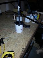
Today I measured my 4FE35 in a sealed chamber. Its made from PVC pipe fittings with 3.5" internal diameter, a good match to the seating rim provided on the driver for mounting to the front of a baffle. I'm making a similar chamber with a mailing tube for the 3FE25s
When building it, I was concerned that the response would be affected by the magnet (2.8" dia.) almost completely filling the pipe, that the driver wouldn't see or feel the cavity in back of the mirror. The measurements show that this is indeed the case. I calculate .54L volume, which should yield a peak at (Fbox) of 232 Hz but instead get a peak at 345-365 Hz (two diff measurements). This tune corresponds to box volume of .15L but I imagine what I really have is a bandpass system with a port between two chambers.
I thought I would pass along the caution because the fit in a 3" mailing tube for the 3FE25 is even tighter and could impact what you are doing. I'm hoping you are motivated to model the chamber in ABEC as I'm not there yet in terms of being able to do it myself. I'm waiting for the glue to dry on the 3FE25 chamber and will have a measurement on it before long.
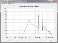
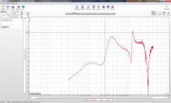
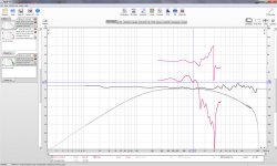
I've attached the horn resp sim results and a screen shot from REW of a clos mic measurement. In the HR, the grey trace is for a .54L chamber and the black is the chamber volume adjusted to match the peak frequency in the measurement. Note the nasty resonances as well.
Jack
Hi CookieMonster:
Today I measured my 4FE35 in a sealed chamber. Its made from PVC pipe fittings with 3.5" internal diameter, a good match to the seating rim provided on the driver for mounting to the front of a baffle. I'm making a similar chamber with a mailing tube for the 3FE25s
When building it, I was concerned that the response would be affected by the magnet (2.8" dia.) almost completely filling the pipe, that the driver wouldn't see or feel the cavity in back of the mirror. The measurements show that this is indeed the case. I calculate .54L volume, which should yield a peak at (Fbox) of 232 Hz but instead get a peak at 345-365 Hz (two diff measurements). This tune corresponds to box volume of .15L but I imagine what I really have is a bandpass system with a port between two chambers.
I thought I would pass along the caution because the fit in a 3" mailing tube for the 3FE25 is even tighter and could impact what you are doing. I'm hoping you are motivated to model the chamber in ABEC as I'm not there yet in terms of being able to do it myself. I'm waiting for the glue to dry on the 3FE25 chamber and will have a measurement on it before long.
I've attached the horn resp sim results and a screen shot from REW of a clos mic measurement. In the HR, the grey trace is for a .54L chamber and the black is the chamber volume adjusted to match the peak frequency in the measurement. Note the nasty resonances as well.
Jack
Attachments
Not so much WAF - but at least they don´t need one meter to each wall like my current speakers.
Looks great. Where is/are the subwoofer(s)?
IMO, the worst case isn't not getting the predicted support, its getting a boundary null in the passband. which is why I would place my woofers outside the horn, D'Appolito style, were it not for how tall the speaker would then have to be.
If anyone is interested in building a D'Appolito with waveguides, David Smith did just that for Snell and he's a regular contributor to the forum. His pseudonym is "speakerdave" and he's building commercial arrays to this day.
Here's the Snell:
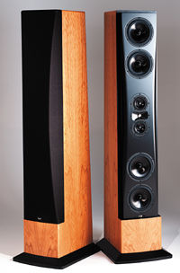
As noted, they are dreadfully tall
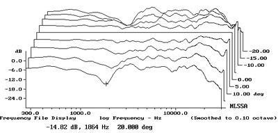
Here's the vertical polars of the Snell. The only real issue is a blip at 2khz. I would speculat that it's an artifact, caused by the fact that the waveguide on the tweeter is only sufficient to control directivity down to about 4khz. And easy solution to that would be to simply stick a very small Synergy horn in the location where the midranges and the tweeters are in the Snell. For instance, a 7" waveguide would control directivity down to 2khz. That would fix the blip in the directivity.
Now, obviously, waveguides control directivity better than arrays do. And I've heard SH-50s and they're rather magical. But trying to fit them into the décor is a challenge. The Snell has better WAF.
Cookie, those look nice. You can improve the WAF of course by adding a grille across the horn. And I think that some SOs would actually prefer larger speakers against the walls to less large ones that sit out 4 feet into the room!
Hey Bill, never noticed you're in Portland now.
I found my first Unity horn in Beaverton; literally emailed the owner out of the blue, hoping he'd let me give them a listen! (He did.)
Vance Dickason is in the area too, over in Lake Oswego IIRC
Where is/are the subwoofer(s)?
Attachments
CookieMonster:
You had a long and productive day yesterday!
Is that what your finished design will look like? I had to look twice to see whether it was a photo or a rendition, but ultimately the emptiness of the room was the giveaway
My 90 degree corner horns tuck more tightly into the corner than yours but when I put them up on their Jubilee-like base bins, they are still hard to miss. Nothing one can do about the fact that size matters.
Are you going to extend your mesh to include the room? I guess that would/should be a separate simulation...nice that ABEC can do that too.
Jack
Well, it´s difficult to say if I will ever have the woodworking skills to put this together. I suppose for me it will be necessary to get them CNCd. Just added bracing and access holes on the back and sides, so it´s going to be a lot of parts, even if I try to minimize it.
The tradeoff I suppose is that if you run a two-way corner variant, you need to have the bass bins pretty close. If you go three way, subwoofers can be out of the way - but then the horns themselves get more intrusive..
I don´t know if I will do room sims. I have requested as a feature that you can split the sim into pieces based on subdomains, and not have to re-solve every subdomain. That would enable moving the speaker around and not wait hours to see what happens. I think it will end with the "infinite baffle" sim, with a guess to what happens when I stick it in a corner: Some wraparound/cancellation around the "baffle step" frequency, and then increased sensitivity as the corner walls kicks in. Floor will be improblematic in this setup, but ceiling bounce will cause some issues etc..
I hope to hide subwoofers somewhere clever, like the tv bench we have - rebuild that and make it inconspicuous.
Cookie, those look nice. You can improve the WAF of course by adding a grille across the horn. And I think that some SOs would actually prefer larger speakers against the walls to less large ones that sit out 4 feet into the room!
Yes, grilles, or colour the insides with a bright green or something.
Man, if I was rich and didn´t have neighbours I would do something like this in an infinite baffle setup.
Hi CookieMonster:
Today I measured my 4FE35 in a sealed chamber. Its made from PVC pipe fittings with 3.5" internal diameter, a good match to the seating rim provided on the driver for mounting to the front of a baffle. I'm making a similar chamber with a mailing tube for the 3FE25s
When building it, I was concerned that the response would be affected by the magnet (2.8" dia.) almost completely filling the pipe, that the driver wouldn't see or feel the cavity in back of the mirror. The measurements show that this is indeed the case. I calculate .54L volume, which should yield a peak at (Fbox) of 232 Hz but instead get a peak at 345-365 Hz (two diff measurements). This tune corresponds to box volume of .15L but I imagine what I really have is a bandpass system with a port between two chambers.
I thought I would pass along the caution because the fit in a 3" mailing tube for the 3FE25 is even tighter and could impact what you are doing. I'm hoping you are motivated to model the chamber in ABEC as I'm not there yet in terms of being able to do it myself. I'm waiting for the glue to dry on the 3FE25 chamber and will have a measurement on it before long.
I've attached the horn resp sim results and a screen shot from REW of a clos mic measurement. In the HR, the grey trace is for a .54L chamber and the black is the chamber volume adjusted to match the peak frequency in the measurement. Note the nasty resonances as well.
Jack
Thanks! What kind of front chamber/exit are you using? Are you measuring this in a horn, or by itself? If by itself, one a big flat baffle?
Look forward to seeing your 3FE25 measurements!
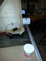
Photo shows how I measured.
Later I screwed that chamber down onto the horn but I couldn't get a good measurement as the garage was fully loaded and the weather precluded me emptying it out. It looked promising though with the mic all the way down the horn throat, like a clos mic.
That horn now has ~28 sq cm, .5" wide slots with round ends for mid ports. That is more than I need. I will fill it in partially with plumbers putty during next measurement process.
I got lazy so 3FE25 measurements will be tomorrow.
I'm not helpless on a table saw but I'm having my cabinets CNCed because I want them to look pretty when done. Funny thing is though, we are doing the horn bevels on a Delta Unisaw in the CNC shop. Unless you have a router V-bit with right angle it takes too long on the CNC.
Jack
Attachments
Hey Bill, never noticed you're in Portland now.
I found my first Unity horn in Beaverton; literally emailed the owner out of the blue, hoping he'd let me give them a listen! (He did.)
Vance Dickason is in the area too, over in Lake Oswego IIRC
Yup, moved here last October. Are you really in San Diego like your sig says? I thought you said Seattle or BC or something like that?
Some wraparound/cancellation around the "baffle step" frequency, and then increased sensitivity as the corner walls kicks in. Floor will be improblematic in this setup, but ceiling bounce will cause some issues etc..
I hope to hide subwoofers somewhere clever, like the tv bench we have - rebuild that and make it inconspicuous.
I investigated several subwoofer concepts with ABEC. The document is in german, but I think the pictures and measurements are self-explanatory.
The best solution are of course a DBA and a damped SBA. this is why I built a a damped SBA in my home theater. Maybe these measurements can help you finding the best subwoofer concept for your synergy horn.
- Status
- This old topic is closed. If you want to reopen this topic, contact a moderator using the "Report Post" button.
- Home
- Loudspeakers
- Multi-Way
- Synergy horn - 3d printing entry?