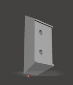
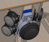
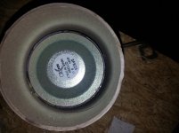
Photo shows how I measured.
Later I screwed that chamber down onto the horn but I couldn't get a good measurement as the garage was fully loaded and the weather precluded me emptying it out. It looked promising though with the mic all the way down the horn throat, like a clos mic.
That horn now has ~28 sq cm, .5" wide slots with round ends for mid ports. That is more than I need. I will fill it in partially with plumbers putty during next measurement process.
I got lazy so 3FE25 measurements will be tomorrow.
I'm not helpless on a table saw but I'm having my cabinets CNCed because I want them to look pretty when done. Funny thing is though, we are doing the horn bevels on a Delta Unisaw in the CNC shop. Unless you have a router V-bit with right angle it takes too long on the CNC.
Jack
I am wondering if your measurement method gives you the strange result.
My completely unscientific hypothesis is that super-close mic will work well with long wavelengths, but not with high, as there will be a phase difference between the sound arriving from different parts of the cone. I did not try this, so perhaps I´m wrong, but I have a feeling you will get a better measurement by either mounting the driver in a big baffle and measuring at a distance where the relative path lengths from various places on the cone to the mic is insignificant, or measuring with the front chamber in place, to ensure that what comes out is already filtered.
Ok - you did measure it in a horn. I suppose you don´t need that much free space if you window your measurement to above 200-300Hz for example? That´s the important bit here. Perhaps the microphone down there creates some reflections that show up in your measurements?
My measurement technique leaves a lot to be desired due in part to the compromise location in which they are performed but at least the clos mic should be reasonably accurate. I did the clos mic because I found the "in the horn" measurements were questionable due to early reflections even with a 3 ms gate. At least I got a sanity check.
Fmax for a nearfield has been analyzed. D'Appolito quotes Keele's formula in his book "Testing Loudspeakers" and he does reference phase shift across the cone. Ironically, that was my first clue that offset mid ports on a large speaker would be a problem.
Fmax = 10950/D where D is piston diameter in cm.
Fmax works out to 1771 Hz for the 3FE and 1400 Hz for the 4Fe buy only 615 Hz for the 8FE200
So I trust that nearfield measurement out past my intended 950 hz crossover point and my questionable in horn measurements suggest its not low pass filtered too much when put on the horn
I just came in from shoveling snow which is already turning to slush and will be gone by tomorrow. This is North Carolina where we get very little snow and people think temperatures below freezing are extreme")
So I will do "proper" measurements probably tomorrow. Inside an empty garage, I can get a pretty good groundplane measurement with the horn lying on the garage floor, tilted forward slightly. Measurements are actually cleaner up in my HT_to_be room but my wire doesn't tolerate loud sweeps very well.
Jack
Fmax for a nearfield has been analyzed. D'Appolito quotes Keele's formula in his book "Testing Loudspeakers" and he does reference phase shift across the cone. Ironically, that was my first clue that offset mid ports on a large speaker would be a problem.
Fmax = 10950/D where D is piston diameter in cm.
Fmax works out to 1771 Hz for the 3FE and 1400 Hz for the 4Fe buy only 615 Hz for the 8FE200
So I trust that nearfield measurement out past my intended 950 hz crossover point and my questionable in horn measurements suggest its not low pass filtered too much when put on the horn
I just came in from shoveling snow which is already turning to slush and will be gone by tomorrow. This is North Carolina where we get very little snow and people think temperatures below freezing are extreme
So I will do "proper" measurements probably tomorrow. Inside an empty garage, I can get a pretty good groundplane measurement with the horn lying on the garage floor, tilted forward slightly. Measurements are actually cleaner up in my HT_to_be room but my wire doesn't tolerate loud sweeps very well.
Jack
Last edited:
STL files if anybody wants to have a look / try to print, suggest improvements.
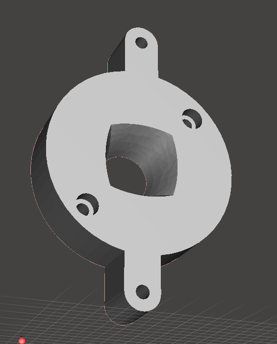
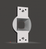
1) Mounting plate for CD, incl beginning of QTWG:
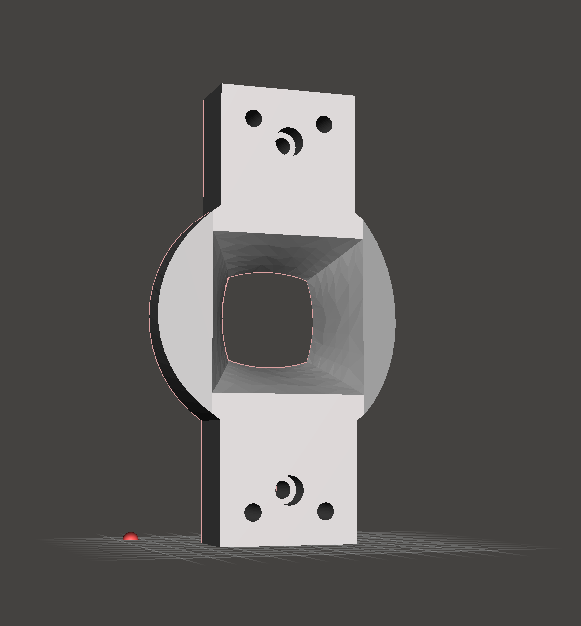
2) Rest of QTWG:
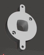
3) Mounting wedge:

Note: Part 3 needs 16mm MDF on a 60x60 horn, and I would expect some sanding etc to make it fit. It won´t fit with thicker materials, but with thinner it will work I suppose - it will just have one surface less to glue it on to. However, it´s a part that doesn´t have to be printed - just make sure you can mount the part 1 + part 2 assembly on the wood.
I have tried to avoid angled cuts as much as possible, so the adapter expects 30 degree angles on the sides. However, the top and bottom flares need to be cut at an angle.

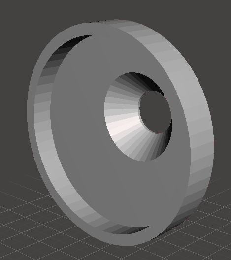
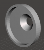
And the midrange adapter. As simple as it is now, I suppose there is not much benefit to it - it doesn´t have much leeway on exit position, but at least it´s quick to swap it later if a more phase-plug-ish variant is needed. I think this part is the least simple to print too - so it might need to be redone unless I want to print this from shapeways or something.
1) Mounting plate for CD, incl beginning of QTWG:
2) Rest of QTWG:
3) Mounting wedge:
Note: Part 3 needs 16mm MDF on a 60x60 horn, and I would expect some sanding etc to make it fit. It won´t fit with thicker materials, but with thinner it will work I suppose - it will just have one surface less to glue it on to. However, it´s a part that doesn´t have to be printed - just make sure you can mount the part 1 + part 2 assembly on the wood.
I have tried to avoid angled cuts as much as possible, so the adapter expects 30 degree angles on the sides. However, the top and bottom flares need to be cut at an angle.
And the midrange adapter. As simple as it is now, I suppose there is not much benefit to it - it doesn´t have much leeway on exit position, but at least it´s quick to swap it later if a more phase-plug-ish variant is needed. I think this part is the least simple to print too - so it might need to be redone unless I want to print this from shapeways or something.
Attachments
-
 2015-02-17 21_27_33-Autodesk Meshmixer - cd_mount_part2.STL.png35.3 KB · Views: 650
 -
 2015-02-17 21_27_56-Autodesk Meshmixer - cd_mount_part3.STL.png18.1 KB · Views: 602
 -
 2015-02-17 21_28_18-Autodesk Meshmixer - cd_mount_part1.STL.png24.7 KB · Views: 603
 -
STL snapshot 20150217.zip70 KB · Views: 66
-
 in horn2.png288.8 KB · Views: 611
 -
 2015-02-17 21_42_45-Autodesk Meshmixer - midrangeadapter.STL.png23.1 KB · Views: 613
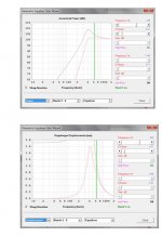
Nearfield measurement of 3FE25
My nearfield measurement of the 3FE25 in a minimum-volume mailing tube cap agrees closely with HR simulation of it as a direct radiator and shows it being good for crossover around 400 Hz.
First attachment compares simulated FR to measured, nearfield
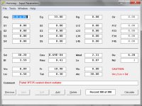
2nd attachment is the simulation model
3rd attachment is the response with a 2nd order highpass at 635 hz which, due to the peak, makes it flat down to 400 Hz.
Jack
My nearfield measurement of the 3FE25 in a minimum-volume mailing tube cap agrees closely with HR simulation of it as a direct radiator and shows it being good for crossover around 400 Hz.
First attachment compares simulated FR to measured, nearfield
2nd attachment is the simulation model
3rd attachment is the response with a 2nd order highpass at 635 hz which, due to the peak, makes it flat down to 400 Hz.
Jack
Attachments
choked off mailing tube
If you want to use the 3FE25 lower than 400 Hz you need more chamber volume and, with an extended chamber, some issues arise. The mailing tube chamber is choked off by the magnet structure. Making the tube longer results in two chambers connected by a port consisting of the gap between the magnet and the tube wall. The measurements aren't pretty, I'll show some next post. They suggest to me to either work with the 400 hz crossover or print some kind of cap that extends out to the side away from the CD to get more volume.
If you want to use the 3FE25 lower than 400 Hz you need more chamber volume and, with an extended chamber, some issues arise. The mailing tube chamber is choked off by the magnet structure. Making the tube longer results in two chambers connected by a port consisting of the gap between the magnet and the tube wall. The measurements aren't pretty, I'll show some next post. They suggest to me to either work with the 400 hz crossover or print some kind of cap that extends out to the side away from the CD to get more volume.
Attachments
I am wondering if you could try to stuff the bigger chamber with some damping material.
I started thinking perhaps this is relevant:
A tube is a pretty good resonator. But - it´s not really a tube anymore when most of the space is filled with something I suppose.
I started thinking perhaps this is relevant:
A tube is a pretty good resonator. But - it´s not really a tube anymore when most of the space is filled with something I suppose.
Attachments
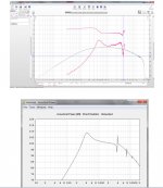
extended chamber measurements
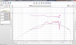
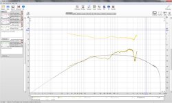
The first attachment is a clos mic measurement with the 3.5" overall height tube sealed and unstuffed. The plug at the end is 1/2" thick so this leaves about 1.25" behind the magnet.
The second attachment is with the tube sealed into a 2' long pipe, fullyu stuffed with poly and unsealed at the bottom (but sitting on a surface so not really open either).
I haven't had much time to think about it so I'll not speculate about why this looks the way it does. This is what I got.
Attachments
CM:
I was ahead of you on the stuffing, just didn't type fast enough. Let me add though that stuffing that small extension just behind the driver made very little difference. The long stuffed tube made a big difference. The problem is, I think, that if the space is too small then you can't get enough damping in it to kill the reflection/resonance.
I can measure a specific stuffed length tube if you want
Jack
Hi CM:
Different approach to the crossover to the woofer for the 3FE25
...instead of a highpass filter I just used a PEQ to flatten the peak at Fbox. Below the flattened peak is a perfect -12db per octave roll off with 6 db down at 300 hz. More like what you were looking for?
The same approach indicates I can cross over to 4FE35's as low as 250Hz with the minimum volume chambers. In both cases excursion stays under control because of the tight air spring. I think I may be ready to declare victory.
Jack
this morning, I'm thinking more clearly.
Yes, of course the long unsealed tube version was a resistance box of some kind. I was hoping there would be so much resistance I could ignore that aspect of it. Thinking about that is a distraction as it served its purpose in proving that the bad artifacts in the measurement were some kind of chamber resonance effect.
Simulating those small volume chambers on the horn, I see no reason not to go with the volume that results from sealing the tube at the back against the magnet structure, before any chamber resonance effects can occur in band. The larger volumes I originally targeted result in less peaking at Fbox but more excursion below it and therefore you don't get to crossover woofer to mids at a lower frequency, nor should you want to in a 3-way.
The only question is how to do seal the back end of the tube. I'm thinking using a bead of latex caulk to fill the gap between magnet structure and tube wall, but I'm open to suggestions. Leaving the back open should help heat dissipate.
The next order of business is to get a full set of drivers on the horn!
The 3" end caps used in Speaker Scott's build seem to work well. That Dayton mid has a 70mm diameter magnet so they are pretty close to the same size as the Faital 3FE25.
Synergy Horns-Dayton and PRV..... - Page 4 - AVS | Home Theater Discussions And Reviews
Synergy Horns-Dayton and PRV..... - Page 4 - AVS | Home Theater Discussions And Reviews
3" PVC pipe is a good fit to the 3FE25. It is 3" ID and 3.5" OD
3" cardboard mailing tubes also work with the 3Fe
3" PVC pipe couplings and caps are a good fit to the 4FE35 as they have a 3.5" ID. When I dry fit the coupling to the 4FE35, I see a gap of about .25" all the way around at the back. That might be a little bit too wide to just fill with caulk so I'm reconsidering. A cap fitting is just a little too short to fit over top of a 4FE35, it needs to be extended by a slice of a coupling.
I built my first chamber for the 4FE35, the one that is too tall and has resonances, by hot-melt gluing the rim of the coupling to the base of the driver. I should be able to take it apart with a heat gun. Too much heat though and the gasket on the driver distorts. I think I'll just cut this down to size on my miter saw. My local Home Depot is out of caps....
I built the chamber for the 3FE25 by gorilla-gluing the tube to the frame of the driver, without first removing that thin foam gasket. The gap at the back of it looks small enough that caulk should work.
My day job is going to get in the way of me doing much more with this today.
Jack
For my test with 3FE25 I just took some latex caulk and filled in between the magnet and mailing tube. Have to be careful that the caulk doesn't drop into the driver (set it upside down after applying), and the process is kind of hard to undo if you're just experimenting. But it makes a nice little sealed-back driver when you're done.
For my test with 3FE25 I just took some latex caulk and filled in between the magnet and mailing tube. Have to be careful that the caulk doesn't drop into the driver (set it upside down after applying), and the process is kind of hard to undo if you're just experimenting. But it makes a nice little sealed-back driver when you're done.
that was my plan, glad to hear that is what you had success with.
Hi CM:
Different approach to the crossover to the woofer for the 3FE25
...instead of a highpass filter I just used a PEQ to flatten the peak at Fbox. Below the flattened peak is a perfect -12db per octave roll off with 6 db down at 300 hz. More like what you were looking for?
The same approach indicates I can cross over to 4FE35's as low as 250Hz with the minimum volume chambers. In both cases excursion stays under control because of the tight air spring. I think I may be ready to declare victory.
Jack
Hi Jack,
I was just thinking. Would you send the full bass signal to these mids? I understand that the small rear chamber will effectively filter out low frequencies, but won´t the signal still travel to the driver and cause rapid heat-buildup or other nasty effects?
Of course, you could put steep high pass outside your bandpass area so it won´t influence the shape of your band pass but still remove much bass content.
- Status
- This old topic is closed. If you want to reopen this topic, contact a moderator using the "Report Post" button.
- Home
- Loudspeakers
- Multi-Way
- Synergy horn - 3d printing entry?