Hi Jack,
I was just thinking. Would you send the full bass signal to these mids? I understand that the small rear chamber will effectively filter out low frequencies, but won´t the signal still travel to the driver and cause rapid heat-buildup or other nasty effects?
Of course, you could put steep high pass outside your bandpass area so it won´t influence the shape of your band pass but still remove much bass content.
That is a good question and a good point about power consumption and intermodulation. While my post was titled "different approach to the crossover", it was really about how I determined how low I could use the drivers and, yes, a suggestion that the resulting slope would be a good match to a classic high pass on a woofer. The simulation also shows that a high pass isn't needed for protecting the driver from over excursion.
I don't think power consumption will matter much because of the high efficiency. The power fed to them may be broadband but there won't be very much of it. Intermodulation will be a factor though. I think that ultimately there should be a high pass function in there somewhere. Whether its well below crossover or part of it remains to be determined with the criteria being how one gets the best transition between mid and woofer and of course the best sound.
Let's not forget that we are chasing that elusive goal of flat phase across the entire passband. The architecture of the crossover in general and how we go about flattening that peak in particular does affect the final phase. The chamber volume must have some effect on that final phase because its clear that increasing the volume reduces the peaking and lowers the Fbox. Unfortunately the easy choice of using pipes sealed against the magnet structure to create a chamber foregoes the option of tuning the chamber volume. Thinking about this, I realize I might not be quite done yet.
Jack
Ok, here is the latest. I imported the 8FE200 into the BEM part of the model.
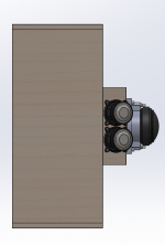
Woofers:
It sims very nicely with a 16mm spacer (same thickness as the MDF I plan to use) to increase chamber volume. 55mm entry holes. 6 liter rear chamber per driver is used here. The cone profile is a guestimate based on the data sheet.

Response pre-crossover (100 measuring data points over 5 octaves)
After LR4 @ 400hz:
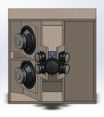
Mids:
Mids (3FE25, 8 ohm) using the 0.09 liter volume estimated by nc535 (tight mailing tube, magnet to seal off). Note: Sim is for centered entry hole, slight offset must be used. I don´t think it´s an issue - the bandwidth even after the offset will be higher than the reflection frequency.
Lowering mids 5dB, adding LR4@400Hz and LR4@1300Hz gives this:
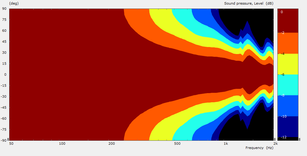
Simulated directivity on infinite baffle (normalised, so some "hash" after the midrange is done, just some low-SPL reflections being scaled up)
Woofers:
It sims very nicely with a 16mm spacer (same thickness as the MDF I plan to use) to increase chamber volume. 55mm entry holes. 6 liter rear chamber per driver is used here. The cone profile is a guestimate based on the data sheet.
Response pre-crossover (100 measuring data points over 5 octaves)
After LR4 @ 400hz:
Mids:
Mids (3FE25, 8 ohm) using the 0.09 liter volume estimated by nc535 (tight mailing tube, magnet to seal off). Note: Sim is for centered entry hole, slight offset must be used. I don´t think it´s an issue - the bandwidth even after the offset will be higher than the reflection frequency.
Lowering mids 5dB, adding LR4@400Hz and LR4@1300Hz gives this:
Simulated directivity on infinite baffle (normalised, so some "hash" after the midrange is done, just some low-SPL reflections being scaled up)
Attachments
-
 2015-02-23 21_03_29-ABEC3 - ABEC Synergy8, 8 8FE200.png49.7 KB · Views: 851
 -
![2015-02-23 21_16_44-VacsViewer - (new) - [SPL].png](/community/data/attachments/437/437939-dfce2e105a9eed1662113fd9fe662b59.jpg) 2015-02-23 21_16_44-VacsViewer - (new) - [SPL].png45.5 KB · Views: 851
2015-02-23 21_16_44-VacsViewer - (new) - [SPL].png45.5 KB · Views: 851 -
![2015-02-23 21_20_30-VacsViewer - (new) - [SPL].png](/community/data/attachments/437/437952-12ac59c76b183d3c56e5ab979f0eabaa.jpg) 2015-02-23 21_20_30-VacsViewer - (new) - [SPL].png41.7 KB · Views: 836
2015-02-23 21_20_30-VacsViewer - (new) - [SPL].png41.7 KB · Views: 836 -
![2015-02-23 21_25_13-VacsViewer - (new) - [SPL].png](/community/data/attachments/437/437960-b94c821825c6ab91b9e0a032e5a3e1c7.jpg) 2015-02-23 21_25_13-VacsViewer - (new) - [SPL].png41.9 KB · Views: 843
2015-02-23 21_25_13-VacsViewer - (new) - [SPL].png41.9 KB · Views: 843 -
![2015-02-23 21_31_37-VacsViewer - (new) - [SPL].png](/community/data/attachments/437/437982-4893cf0a76829cd9ef70cd1e58f765b4.jpg) 2015-02-23 21_31_37-VacsViewer - (new) - [SPL].png44.3 KB · Views: 854
2015-02-23 21_31_37-VacsViewer - (new) - [SPL].png44.3 KB · Views: 854 -
![2015-02-23 21_39_22-VacsViewer - (new) - [Directivity].png](/community/data/attachments/438/438004-606cdb85cacf633daa23fb851419a888.jpg) 2015-02-23 21_39_22-VacsViewer - (new) - [Directivity].png29.9 KB · Views: 849
2015-02-23 21_39_22-VacsViewer - (new) - [Directivity].png29.9 KB · Views: 849
Hi CM:
It looks like you are on the home stretch!
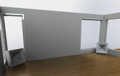
With 4 8FE200's instead of the two I originally planned you should have plenty of bass headroom, especially since you are going to use them in corners.
Do you have any equalization in the crossover? Looking at your waveforms, I see your mids don't have the peak at Fbox that my HR sims show and, while I don't think that is due to the difference between SPL and HR's acoustic pressure, I would like to see how close HR can be made to come to your simulation. Could you get ABEC to create an acoustic pressure waveform?
Phase waveforms would also be interesting. My mids show a peak in group delay coincident with the peak in acoustic pressure at Fbox. If I increase the chamber volume, I can move that peak down below crossover, which should help with keeping the phase flat. Did you have to deal with that peak in group delay? I'm tempted to increase the chamber volume for my 4Fe35's to 2L for 4 chambers for that reason. With that much volume I'm forced to use a high pass to prevent over excursion but doing so allows me to move the crossover down to 200 Hz.
I see your woofer ports are round. Others have used rectangular ports with round ends to keep closer to the corners. Did you try other port shapes? With the BEM simulation you could try other shapes... if your computer needs something to do overnight")
Jack
It looks like you are on the home stretch!
With 4 8FE200's instead of the two I originally planned you should have plenty of bass headroom, especially since you are going to use them in corners.
Do you have any equalization in the crossover? Looking at your waveforms, I see your mids don't have the peak at Fbox that my HR sims show and, while I don't think that is due to the difference between SPL and HR's acoustic pressure, I would like to see how close HR can be made to come to your simulation. Could you get ABEC to create an acoustic pressure waveform?
Phase waveforms would also be interesting. My mids show a peak in group delay coincident with the peak in acoustic pressure at Fbox. If I increase the chamber volume, I can move that peak down below crossover, which should help with keeping the phase flat. Did you have to deal with that peak in group delay? I'm tempted to increase the chamber volume for my 4Fe35's to 2L for 4 chambers for that reason. With that much volume I'm forced to use a high pass to prevent over excursion but doing so allows me to move the crossover down to 200 Hz.
I see your woofer ports are round. Others have used rectangular ports with round ends to keep closer to the corners. Did you try other port shapes? With the BEM simulation you could try other shapes... if your computer needs something to do overnight
Jack
There is no equalization. Including that in ABEC is a bit complex, as you need to enter biquad-like functions, and to see the shape of it I need to play with Active Crossover Designer or another tool. If you know of a tool that gives analogue parameters for all these functions let me know. I had to resort to the Digital EQ Cookbook to try to find out how to make a shelving filter for instance. Regular textbook filters are easy in ABEC - but it´s not a crossover designer tool in itself. I guess I will use ADC once I have measurements.
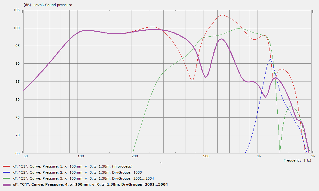
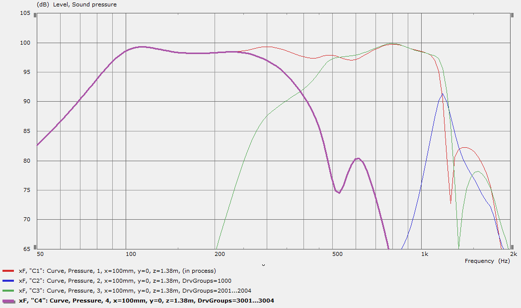
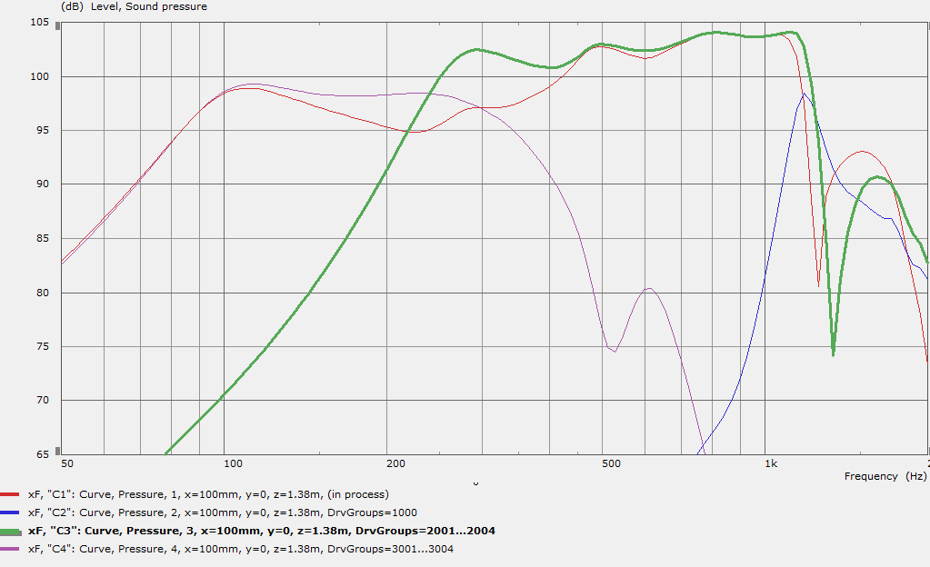
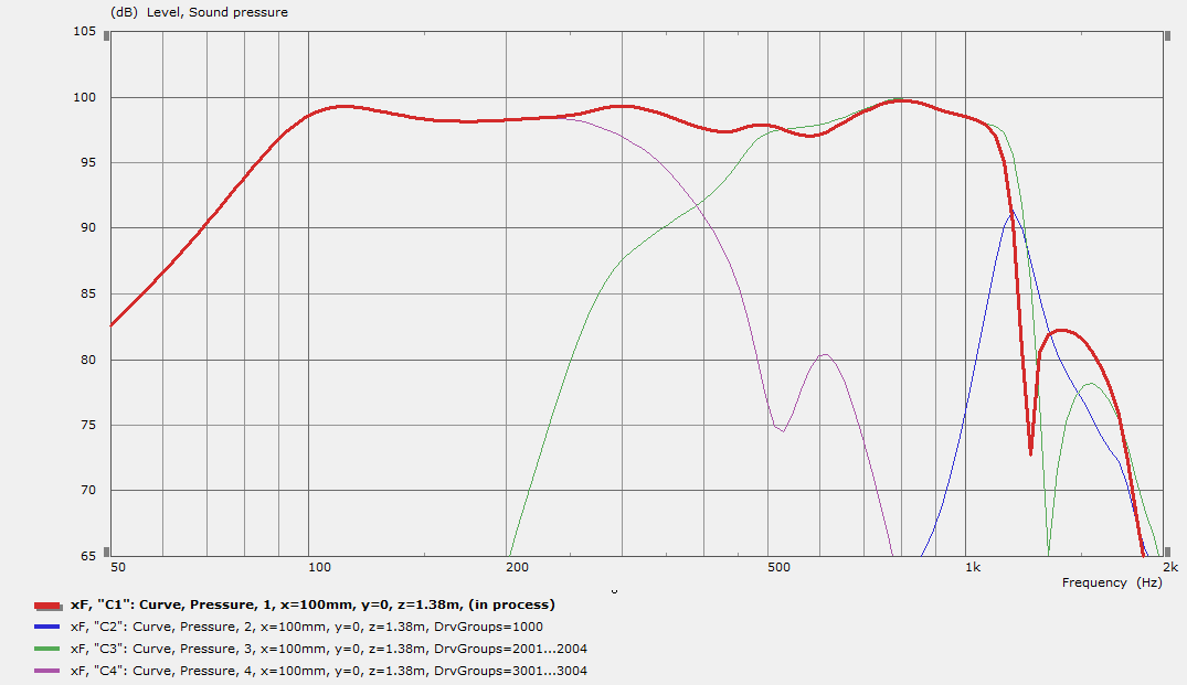
See if these charts answer your questions:
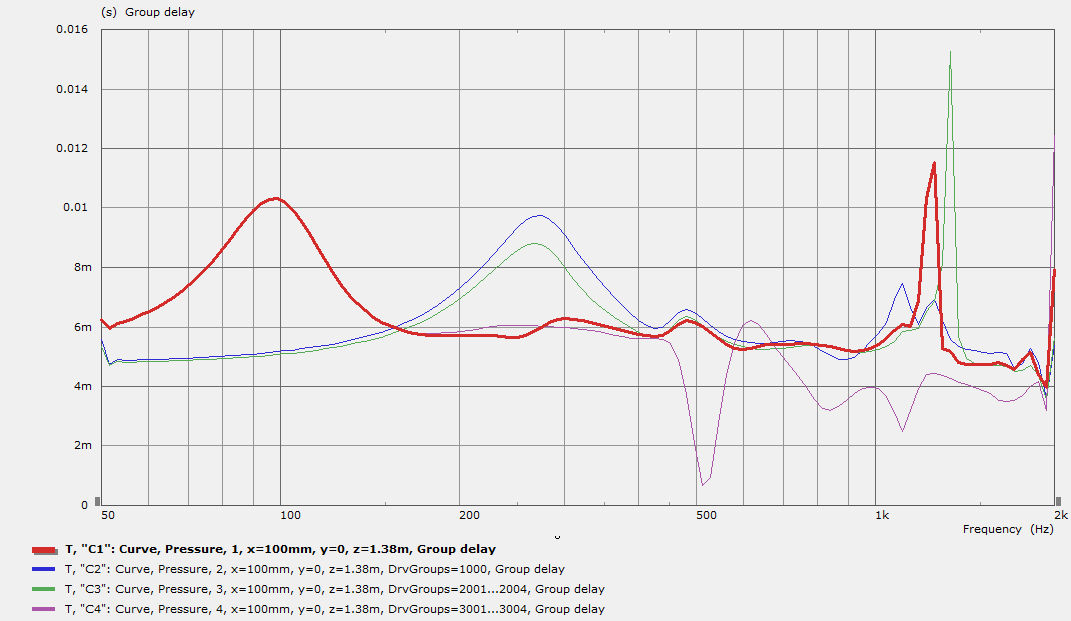
Red is total response, green is midranges, purple is woofers.
Ignore the blue one - I believe it is the reflection from the "dead" CD.
Group delay
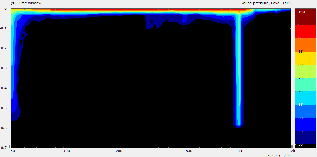
Decay spectrum
Phase:
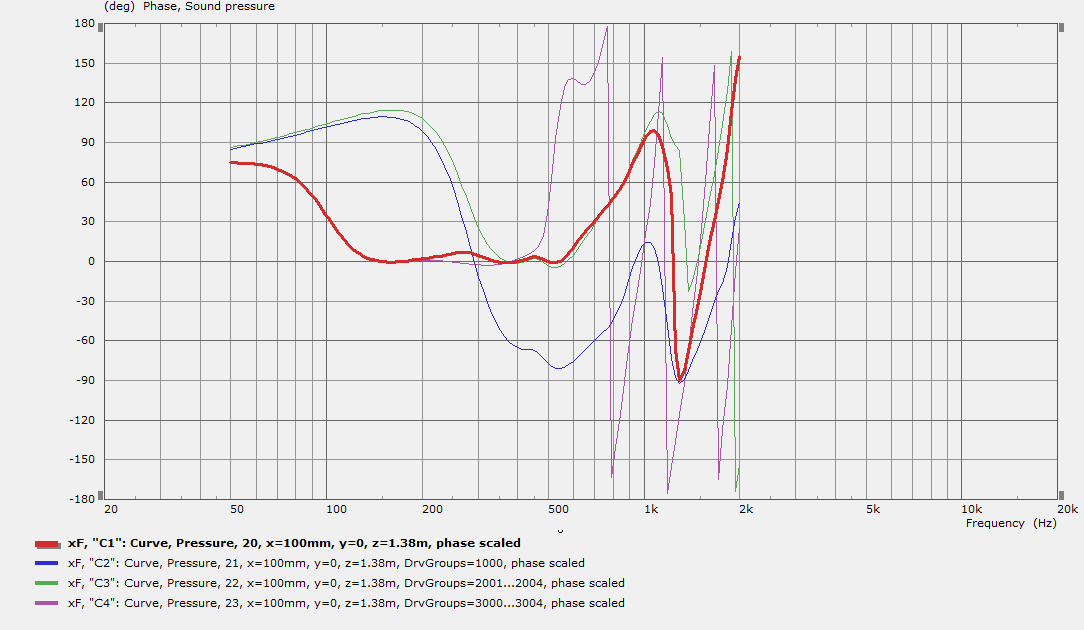
The phase chart is shifted by -2.03m. I am not sure if I´m doing this correctly, but if I don´t do this its just rotation after rotation, and the figures seem to make sense. I also shifted the curves to fit on one screen (so that the response from 150hz up to 500hz is at 0 degrees).
These are "after crossover" results. Let me know if you need pre-crossover charts.
I am not sure if ABEC has the rectangle with round corners as a standard building block. But it seems like the compression driver results are not disturbed by the port at that location when that crossover frequency is used, so I don´t think I´ll dig into that. I´m not worried about my computers hard work, rather my own time..
See if these charts answer your questions:
Red is total response, green is midranges, purple is woofers.
Ignore the blue one - I believe it is the reflection from the "dead" CD.
Group delay
Decay spectrum
Phase:
The phase chart is shifted by -2.03m. I am not sure if I´m doing this correctly, but if I don´t do this its just rotation after rotation, and the figures seem to make sense. I also shifted the curves to fit on one screen (so that the response from 150hz up to 500hz is at 0 degrees).
These are "after crossover" results. Let me know if you need pre-crossover charts.
I am not sure if ABEC has the rectangle with round corners as a standard building block. But it seems like the compression driver results are not disturbed by the port at that location when that crossover frequency is used, so I don´t think I´ll dig into that. I´m not worried about my computers hard work, rather my own time..
Attachments
![2015-02-24 15_49_44-VacsViewer - (new) - [SPL].png](/community/data/attachments/438/438997-1f4093b3cf9b017e1623eefbbc8f90ba.jpg)
![2015-02-24 15_53_05-VacsViewer - (new) - [SPL].png](/community/data/attachments/439/439016-8d6a98a0ac491ec86f990e44db6b7943.jpg)
![2015-02-24 15_59_52-VacsViewer - (new) - [Phase].png](/community/data/attachments/439/439021-687c3ffb2d79cbd699327b55b39029ba.jpg)
Thanks.
I like ACD and would use it to generate the parameters. Enter the poles, zeros, Qs etc in the top tab and then one of the inner tabs will give you the biquad coefficients which you can cut and paste into the miniDSP tool. The user manual shows you how to make shelf filters, etc. I've exported from HR into ACD to make trial crossovers.
Your group delay chart is not what I would expect. One would think the peak in group delay at 100 Hz for the total response would be mirrored in the woofer group delay but I don't see that. Its curious that the green and purple group delay traces both peak just below 300 Hz. I would expect the 3FEs with their tiny chambers to peak closer to 400 Hz and the 8FE200 to peak down where the system response peaks.
What a great thread. I was looking at doing a small SH prototype for my first try. About the size of your 3d printer horn. Nothing bigger than that for now. I was looking at FaitalPro HF14AT, BC DE250 and a few other CD's.
I already have some Visaton 3.3" FRS 8M's I planned on using. I can get the 3FE22 or 4FE also. Just thought I would try what I had already. I plan on using whatever is needed for high SPL. So later on I will probably go with the 4FE if it is best.
I plan on using 12's or possibly 15 for bass drivers but that is SO FAR in the future that it doesnt matter. I mainly want to test out some CD mid combo's that will work for the future project. BUT with in reason of my small budget.
So this thread has been a great read. I wish I could simulate all of these drivers but ABEC looks quite complicated. BUT I will try and see if I can learn some more from everyone here.
Great progress CM! Looks fantastic - both design and simulation.
I am looking for a good 3d printing software package. I hear that Simplify 3D is great and consolidates all the little stuff into one integrated seamless package to produce better results compared to cobbling together your own separate freeware open source stuff.
Has anyone used Simplify 3d?
https://www.simplify3d.com
Seems like money well spent to avoid frustration and wasted prints.
I have not tried Simplify 3d.
I use Makerware for slizing and Proftweak to make my own profiles.
Proftweak:
Introducing ProfTweak – a MakerWare profile editor | Nothing Labs
Makerware is simple and fast to use so I don`t want to spend the money on Simplify 3d.
To make more advanced support structures I use MeshMixer.
And I design in Spaceclaim.
But I understand that you like to have one, and only one software to tweak to make better prints.
This:

Reminds me of this:
http://www.diyaudio.com/forums/full-range/261427-presenting-trynergy-full-range-tractrix-synergy.html
Reminds me of this
:
http://www.diyaudio.com/forums/full-range/261427-presenting-trynergy-full-range-tractrix-synergy.html
Its interesting how much of the original plastic horn walls have been replaced by wood.
I think, having followed this progression while working on my own conventional wood solution, that one could take a conventional horn such as my own, run something like a 2" diameter Forstner bit through the apex from the front out through the CD mounting plate and then insert in a 3D printed throat with the ideal expansion and round to rectangular conversion...
I think, having followed this progression while working on my own conventional wood solution, that one could take a conventional horn such as my own, run something like a 2" diameter Forstner bit through the apex from the front out through the CD mounting plate and then insert in a 3D printed throat with the ideal expansion and round to rectangular conversion...
I think there are two extremes here: an all plastic 3d printed horn, and the throat adapter horn that this has become. Much of this progression is due to how expensive it would be to make it completely out of 3d printing, and the workpiece size limits.
I think the middle ground would be a throat adapter/CD mounting flange, and the chamber/throats for the mids with mounting flanges, and the shortened horn body for the other pieces to mount onto. This way, the complex geometry is handled by 3d printing and the workpiece sizes are manageable.
It would really be cool to use the plastic 3d parts as the basis of a lost wax (plastic) casting in aluminum. That would be cool.
I suppose the big difference between your Trynergy and the other picture, is that yours is built and works, and mine is just an idea for now.
You are right - the only reason why I didn´t just print the big one is cost - breaking it up into smaller parts that can be tweaked individually is a way to reduce risk.
I sent the part for printing at a local 3dhubs affiliate, but he´s been rather unresponsive, and I´m very close to demanding my money back. We´ll see how that goes. Worst case for me, it´s money lost, but i suppose for him he´ll get a rather poor review on 3dhubs that I can´t imagine will be good for business. We´ll see how it goes... He was the only one in the neighbourhood that could print ABS (unless you go to the proper prototyping companies which will charge more, that is), which I figured was the material to use for this.
- Status
- This old topic is closed. If you want to reopen this topic, contact a moderator using the "Report Post" button.
- Home
- Loudspeakers
- Multi-Way
- Synergy horn - 3d printing entry?