I was thinking a larger dust cap - 2.5" or 3" would stiffen up the cone and reduce cone flexing.
How did the dust cap removal go? Did some of the cone tear away?
There was a boutique speaker shop here years ago; they used to remove the dust cap, glue in a foam plug and re-install new cap.
How did the dust cap removal go? Did some of the cone tear away?
There was a boutique speaker shop here years ago; they used to remove the dust cap, glue in a foam plug and re-install new cap.
What would a larger dust cap do? The idea was to eliminate it as it was causing the primary offending resonance.
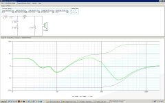
A side benefit, the kink in the impedance at about 800 must have been the pole vent as it diapered. It did not seem to cause any issues, but being gone does not hurt.
Easy to cut out with a razor blade. A dust cap right above the coil former is probably not adding stiffness, it is , errr, a dust cap and an air seal separating the outside from the inside. Sometimes they are aluminum and bonded to the coil former and also function as additional heat sink. Sometimes caps are placed very high up the cone. Is that for stiffness, or to manage phase? You would would have to ask the designer.
My plugs were a wild guess. A well designed phase plug has very precise geometry relationship with the cone. I don't know enough to know how to do that. They need to be reflective. Foam won't work the same way.
Adding foam behind is something totally different. Very common on tweeters. With a dust cap, the voice coil and space behind the cap is vented through a hole in the pole piece. So, yo have another tuneable cavity. Foam will work just like it does in the cabinet.
With the cap removed and a phase plug, it vents out the front.
What I can say is the dustcap was the worst offender in breakup on three different drivers.
Nice little box, I'm guessing its sealed?
Wave guide looks good too.
If only i had a garage....
Rear port. 14L . 2" plastic pipe. I have not bothered to tune the cabinet yet. Somewhere around 6 1/4 inch with one radiused end by calculation. If you plug it, it should be max flat sealed at 80 Hz. I have not measured to verify. The modified driver wants a bigger box. I can probably stretch them to about 16L if I build a pair. For testing, I have them lightly stuffed with cotton batting.
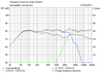
If you look at the FRD, you can see the boost in the lower treble from the waveguide. It does not seem hard to deal with, but I have not built the crossover and have not listened or measured off axis. This was really easy.
Yeah the bump in the low end, is what puts me off trying the same. I don't think its that hard to work with in the crossover, i just lack confidence in my ability to do it. I must get used to PCD. I can manipulate frd and zma into Boxsim,, but its time consuming. Its about time anyway!
Last edited:
I had been scared off any tweeter loading too, but this project is what-the-heck-as-long-as-it-is-cheap. PSD-Lite is a bit rough around the edges, but it seems to correlate well with measurements. I need to learn Sound Easy as I spent the big bucks on it years ago. Every time I try and get through it, I have to start over again.
Time is what a hobby should provide. It should take several months to design a speaker well. It took over a year for the Santori build over in the vendors thread and the results were a FIRST ORDER network. I have got to build me one of those. I am just glad I am not measuring T/S with a generator and VTVM any more, and I can plug the numbers into WinISL instead of working the old White/Bulloc tables, or worse, my own original approximations I made from Dick Small's thesis. We never had it so good.
As luck would have it, the bump did not cause too big of a problem, that is compared to the basic shortcomings of cheap speakers in the first thumbnail design. I have not studied it carefully and have not built it. Darn 9 to 5 job gets into my way but I do like to eat. I could be totally off base, tweeter hump and not curing the breakup. Or I could be stupid lucky and it is great. Only building the crossover will tell.
Reading up on phase plugs today. It seems in this application, all it is is a blockage, so the shape need only not add sharp diffraction points. Just rounding over a dowel should be fine. Fit is likewise not that critical.
I see some discussions about dust caps and thinking might be a good idea since I'm using a 3 set of SF's in the HT.
What do you recommend? Remove caps and make up wood plugs?
Thinking mdf "donuts" rounded over - similar to a lot of drivers, e.g. Peerless woofers have a metal dome added to pole piece.
2. Do not replace dust caps with after-market caps?
(which would look really cool)
What do you recommend? Remove caps and make up wood plugs?
Thinking mdf "donuts" rounded over - similar to a lot of drivers, e.g. Peerless woofers have a metal dome added to pole piece.
2. Do not replace dust caps with after-market caps?
(which would look really cool)
Let me test stock, slit caps, slit and doped caps, against the phase plug. My best guess is doping the cone was not needed and only served to increase required box volume. The rubber surround probably does it's job.
For the plug, anything solid will do. A dowel with a rounded over tip is sufficient. The MDF was very hard to turn down in my drill as it was too flexible. My next ones will be hardwood or Delrin. I happen to have a length left over from making solid suspension bushings for my TVR. The bullet shape is sexy, but not needed.
Busy today with some home repair. All the parts I need for the band saw are on order. I even found blades at Lowes cheaper than online.
Aftermarket caps? If I had a the measurement equipment ( laser inferometry or holographic comparisons) and I wanted to build several thousand drivers, sure I might try to design a cap that does not have the same issues. Check the detail Fostex has worked on to reduce breakup in their caps. Then note that Planet10 still applies his doping pattern to it! I see only one advantage to a dust cap. Keeping dust out of the voice coil. I have to think if a sealed box is a different case causing a higher loss factor due to spyder flex from box pressure as it becomes stressed, rather than the dust cap. A possibility, but not germane to this project.
If you got the cap off, then just round over (1/4" radius should do) a bit of dowel. To clear the glue left after pulling the screen off the pole piece, carve a bit of relief in the back end. Then mount it with a long screw and washer through the pole piece vent. Paint as desired. I went through a lot of trouble to get a very precise side fit, but I am not sure that is really necessary.
So far so good with small disks ")
Long screw - really? Won't a steel bolt change magnetic field or something?
1/4 in.-20 x 3 in. Nylon Hex Bolt-16388 at The Home Depot
Long screw - really? Won't a steel bolt change magnetic field or something?
1/4 in.-20 x 3 in. Nylon Hex Bolt-16388 at The Home Depot
Last edited:
In theory, yes. In practice, not at this level. Use a brass screw if you want. They cost more. I did not use glue as I did not want to risk gluing the voice coil. Remember O BETTER CHEAPER.
I am going to model a few other crossovers this afternoon. Can I make a first order at 2500 work? Not having the Q to play with, my hunch is no, but that is what this is about, finding the cheapest solution.
O BETTER CHEAPER.I am going to model a few other crossovers this afternoon. Can I make a first order at 2500 work? Not having the Q to play with, my hunch is no, but that is what this is about, finding the cheapest solution.
Not at all worried about the tweeter resonance. With the modified woofer, I shifted the crossover up to 2 to 2.5K range. Of course, 5K is more like where I would normally look to do a first order. But in the concept of CHEAP, worth a try. Terrible results. All it cost me was my time.
I also played with best I could do. For about three times the cost, I could model (based on in-box real measurements) within a dB 100 to 10K. 13 parts and reduced the efficiency a couple of dB. Totally out of scope for budget. It can be done.
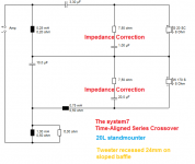
Parts I decided on are 2.7mH and 8.2uF on the woofer, 4.7uF and .55 mH on the tweet with a 5.1/4.7 pad. A little of the 3.3 breakup still shows, and a little of the diffraction hump is still there, but for a CHEAP build, I hope it will be pretty good. This is based on the slit/doped woofer. Bottom end was stronger, box smaller. Almost as good as the phase plug. Easier by a lot. Parts will take about a week to get here, so don't wait up on the results.
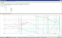
Woofer mod: I cut 6 radial slits from the edge of the cap to about a quarter inch from the center, Then applied a pretty heavy coat of silicone to just the cap. Resonances moved up with the slits, and back down to 3.3K with the silicone, but lower in amplitude by a lot. T/S for the entire driver did not change much.
I also played with best I could do. For about three times the cost, I could model (based on in-box real measurements) within a dB 100 to 10K. 13 parts and reduced the efficiency a couple of dB. Totally out of scope for budget. It can be done.
Parts I decided on are 2.7mH and 8.2uF on the woofer, 4.7uF and .55 mH on the tweet with a 5.1/4.7 pad. A little of the 3.3 breakup still shows, and a little of the diffraction hump is still there, but for a CHEAP build, I hope it will be pretty good. This is based on the slit/doped woofer. Bottom end was stronger, box smaller. Almost as good as the phase plug. Easier by a lot. Parts will take about a week to get here, so don't wait up on the results.
Woofer mod: I cut 6 radial slits from the edge of the cap to about a quarter inch from the center, Then applied a pretty heavy coat of silicone to just the cap. Resonances moved up with the slits, and back down to 3.3K with the silicone, but lower in amplitude by a lot. T/S for the entire driver did not change much.
I make that about 2.6kHz crossover, which is OK. It all looks OK on frequency response too. My modelling is rough and ready, of course.
I still like my 5kHz tank on the woofer, and I think you should try it. Phase isn't IMPORTANT...it is EVERYTHING!
I still like my 5kHz tank on the woofer, and I think you should try it. Phase isn't IMPORTANT...it is EVERYTHING!
Attachments
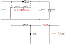
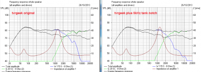
Ah, you are using the unimproved OEM woofer plots. My phase plug or slit/doped version does not have the breakup at 4.4K. (it has a much smaller one at 3.3 I am going to ignore for now) By the model, a notch is not needed there.
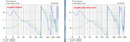
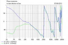
Now on to phase, I am not really sure what I am looking at. I'll gladly take whatever help you can provide.
Now on to phase, I am not really sure what I am looking at. I'll gladly take whatever help you can provide.
Attachments
I was using a TYPICAL 6" paper woofer at heart. Your sliced and doped dustcap is taking you into deep scanspeak water indeed:
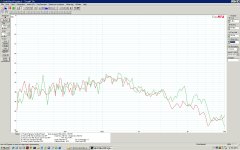
Vibration analysis
I learned more from that article than almost anything I can think of apart from Lynn Olson.
Hard to say what your dustcap mods are doing. They may add a certain amount of rolloff and damping to the AAL3 resonance. You'll have to model it to see what combination of electrical and mechanical damping works best.
Phase is easy, once you get it. Keep the drivers phase aligned throughout the overlap region. I can't explain it more simply. Just occasionally, drivers play beautifully together, as below:
Attachments
- Status
- This old topic is closed. If you want to reopen this topic, contact a moderator using the "Report Post" button.
- Home
- Loudspeakers
- Multi-Way
- Budget build results, SF-Dayton