Hi,
I've no idea if a series baffle step inductor followed by a notch filter
set to 4.5KHz for the SF can be massaged into a viable x/o function,
by manipulation of the notch Q, however it is a very effective technique
in terms of component count if you can get it to work with a peaky driver.
x/o point of course also depends on how low the tweeter can go,
and what is good point to utilise its overall roll-off for x/o function.
rgds, sreten.
Yup, I was hoping it could go low, like the 1500 I selected, but distortion was just too high. Even for the larg-ish 1 1/8 dome. Will the wave guide help enough? Can I sneak it up to 1800? With the doped cone and waveguide, maybe. ( and no extra $10 coils)
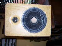
BTW, the exact size for the plug in 1 1/5 inch . Dead on. It is held on with a screw through the pole piece vent. This allowed shifting it around to not rub and is still removable.
It is a tossup between the slit dust cap and the phase plug.
Oh yea, because of the plug, the last picture is about 5 mm further away, level shifted to match.
It is a tossup between the slit dust cap and the phase plug.
Oh yea, because of the plug, the last picture is about 5 mm further away, level shifted to match.

Hmmm. Gains in the response, but now wants a much bigger box. Loss in the bass as the box size is set at 14L. We are still talking F3 in the 60 Hz range which is OK. Even though the raw SF will do 50, that is a lot to ask of a driver this size.
That gives us a big difference to evaluate. Which is a better trade-off?
That gives us a big difference to evaluate. Which is a better trade-off?
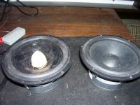
What would a larger dust cap do? The idea was to eliminate it as it was causing the primary offending resonance.
Not having 100 or so drivers to play with, and no laser inferomerty setup to actually see the breakup modes, I am guessing. Slitting the dust cap and doping only it may be the best combination. But, with only one test driver, that is not an option anymore. This is the third driver I have played with that the dust cap was the biggest offender. A Fountek and a Foustex were the others.
A side benefit, the kink in the impedance at about 800 must have been the pole vent as it diapered. It did not seem to cause any issues, but being gone does not hurt.
Playing with the original box simulation ( glue drying on the new box)
A decent looking 2K LR4 acoustic can be had:
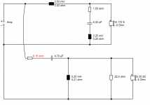
Woofer is second order, 2.5mH, 3,9uf with a 2 ohm, .3mH, 2.2u series notch filter.
Tweet is 9.1uf, .39mH, the pad is 3 and 13 ohms with a .7u in parallel with 3 Ohm, and a 1 ohm, 2.2 series contour. Woofer crossover is about $5.50 more. Tweeter about $3 more. 5 more parts. Starting point.
Anybody else?
A decent looking 2K LR4 acoustic can be had:
Woofer is second order, 2.5mH, 3,9uf with a 2 ohm, .3mH, 2.2u series notch filter.
Tweet is 9.1uf, .39mH, the pad is 3 and 13 ohms with a .7u in parallel with 3 Ohm, and a 1 ohm, 2.2 series contour. Woofer crossover is about $5.50 more. Tweeter about $3 more. 5 more parts. Starting point.
Anybody else?
Here is another version. The series resistor in the tweeter helps keep the network above 6 Ohms. Not sure this would fit on the bottom of the cabinet! It is not a lot more money but it fails in the simple category. I look forward to how much simpler it can be with the new box and/or modified woofer.
Attachments
I never get it at all with your and odougbo's circuits. 
Why on earth do you use an LCR notch AND a shunt capacitor after the bass coil? It's just TERRIBLE on phase above 4.5kHz. 90 degrees out by my reckoning.
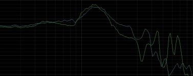
The idea of the notch is to tame the 6.5 inch Silver Flute woofer's main 4.5kHz peak AND line up phase above 4.5kHz. This is cone breakup region, and any phase problems cause the tweeter and woofer to lose integration. It will sound ROUGH!
Below is my guess as to where you should be, with a crossover around 2.6kHz. With any luck, phase will be within 40 degrees right up to 10kHz. That's about as good as you can do with a single notch circuit. It's not enough to just get a flat frequency response.
Why on earth do you use an LCR notch AND a shunt capacitor after the bass coil? It's just TERRIBLE on phase above 4.5kHz. 90 degrees out by my reckoning.
The idea of the notch is to tame the 6.5 inch Silver Flute woofer's main 4.5kHz peak AND line up phase above 4.5kHz. This is cone breakup region, and any phase problems cause the tweeter and woofer to lose integration. It will sound ROUGH!
Below is my guess as to where you should be, with a crossover around 2.6kHz. With any luck, phase will be within 40 degrees right up to 10kHz. That's about as good as you can do with a single notch circuit. It's not enough to just get a flat frequency response.
Attachments
I tried simplifying the LP section as Steve and Mondo mentioned in a previous design and it did not work as well as I had hoped causing some issues in the crossover region. I know, it should not have. So I drew this one up textbook. I did not put any of this into SPICE as I usually do to take a look at the phase response of just the network every step of the way. This was a one-beer design, so it was not aided by extra creativity. I have reached an age where the morning after is not worth the night before.
You are correct that its phase response is not optimum. It is certainly important, but at this end of the cost spectrum, I argue secondary to a basic balance in response. Fix the worst problem first. I don't know if it will sound harsh, but it sure can send the imaging down the drain. Remember, the goal here is CHEAP. The challenge is to do better for less. The first cheap crossover fix is just a 1u cap across the 1 Ohm pad. I am surprised no one mentioned that.
I should be able to get to the new box (waveguide mounted tweeter and modified woofer) measured today. With the new box and modified driver, is it possible to do a first order electrical? Maybe asymmetrical? Less is more. The reason for the complex LR4 was to show it takes a lot of parts to move to the next step. You know, that old 90% rule. The first 90% of a project takes the first 90% of the budget. The last 10% takes the other 90% of the budget.
It should be warm enough to get into the shop in another hour and mount the drivers. Offset and distances are different and the edges are radiused.
 well i exceeded The single beer, so guess was likely closer to stab in the dark.
Creativity is overrated, experience is valuable ��
Looking nice from the teaser though. And i wouldn't have thought of the 1u trick.... I'm not sure i was thinking that clearly lol. I just likened the situation to my previous crossover, and guessed.
Good to see you've nailed it now ��
Last edited:
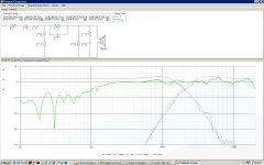
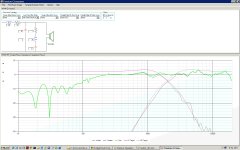
Quick play to see whare I am at with the new box and modified driver.
Target LR4 @ 2K acoustic. Second order electrical. 2.7mH and 9.1uF on the woofer. No filters. Tweeter is series input 2 Ohm, 6.8uF and 3.3mH with 3.9 and 4.7 Ohms pad. Anyway, this is a stab at SIMPLE. All the coil and cap vales are lower, so the cost is quite a bit less. I'll built this for a starting point so I can at least hear it.
Baffle is 9 wide, 12 high. Woofer is 4.5 from the bottom, tweet 9.25 inches. Offset is somewhere around an inch with the tweeter rear mounted .75 inches in.
Attachments
- Status
- This old topic is closed. If you want to reopen this topic, contact a moderator using the "Report Post" button.
- Home
- Loudspeakers
- Multi-Way
- Budget build results, SF-Dayton