There were some very good papers in the old AES anthologies on breakup modes. Without a fancy laboratory, all we can do is tap on it and apply little foam blocks to see what shifts. Pure guesswork. planet_10 hifi has done very well with a generic solution and guesswork. Theories aside, their method absolutely does work.
All I am doing is trying to visualize what may be happening and interrupt it. ScanSpeak does some sort of slit/dope on some of their cones. I have never shelled out the bucks to see what they are doing. It does seem a bit odd to me that the only driver manufacturer who talks about the dustcap breakup in Foustex. There is some irony there. Drivers with phase plugs go on and on about some magical properties, when the blocking effect is probably overshadowed by benefits of lower moving mass and the elimination of dust cap issues. My slit/dope has a negative effect on mms, but it is easier than a phase plug and remains dust-tight. Which tradeoff is best remains at the readers discretion. Both seem to eliminate the need for compensation my electrical means.
One of the problems is the measurement tools don't actually measure phase, rather they all use Hilbert Transform approximations. If you only have the frequency that makes sense. SoundEasy has the benefit of a reference channel. Still, it uses the transform. HOLM does not care. ARTA also has a reference. My mic calibration does not have phase, but I am told it only varies on the outer extremes. I guess I could use SE's HT to generate a phase calibration for it. So, we enter these phase plots into the cad tool, and it guesses from a guess. The guess seems to be pretty good, as the as-built response is not very far off the model.
Thinking out loud here:
If I drove both drivers with separate amps into the passive crossovers,
If I measured the phase with my scope at the preamp output of the mic and the input loop-back,
If I were to adjust the phase via an all-pass filter to one driver so that at the center frequency, I look for maximum amplitude, then at that point, the drivers must be in phase.
Then measure the phase difference between the output of the all-pass and reference,
Sum this with the flight time and it could give actual phase difference.
But why? The sum of two sine waves of the same frequency is still a sine wave. Only the amplitude will vary. As we don't have coaxial point source speakers, the slightest movement off axis will always change the summed amplitude due to flight time difference manifested as a phase shift at that frequency. The end result is still only the summed amplitude. Best science says we don't hear phase, but time/frequency between our ears. So I am not convinced it matters how we get a smooth frequency response. Phase shift in only one tool. Offset is another as it shifts phase with frequency differently than the crossover, so we have two tools. Offset and sloped baffles can help reduce the one phase difference, so I guess that simplifies it. This design reduced the offset by about half and allowed reducing the distance center to center, while increasing the mid-range efficiency of the tweet. All for no dollar expenditure. So, it should have slightly better off-axis response in either plane.
Like everything else in speakers, our understanding frequently falls short of what we hear. Final voicing is always best done with ears. Measurements only help us find the problems quicker. Others may disagree on this of course.
Whew! Time for some coffee. Long night as it was our 40th school reunion. A room full of people who knew each other 40 years ago, and the bar kept turning up the music. Left me rather horse.
Doug,
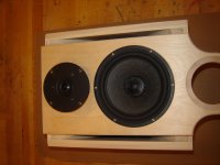
With the higher crossover point allowed by the modified woofer, several other tweeters may work just fine as the ultra low capabilities of the Dayton are no longer necessary. That said, I do not know of a better $20 tweeter anyway. ( anyone else, please chime in) The cheap Vifa's I have are a full step down IMHO. Note, don't get tempted, the crossover is still too low and too shallow for the XT25! My crossover relies on the actual in-baffle measurements. Measurements, here is that ugly word again!
With the higher crossover point allowed by the modified woofer, several other tweeters may work just fine as the ultra low capabilities of the Dayton are no longer necessary. That said, I do not know of a better $20 tweeter anyway. ( anyone else, please chime in) The cheap Vifa's I have are a full step down IMHO. Note, don't get tempted, the crossover is still too low and too shallow for the XT25! My crossover relies on the actual in-baffle measurements. Measurements, here is that ugly word again!
Steve, look carefully at the photo of the teeter-totter driver in the KIPPLE paper. Notice the dustcap.
This is a good short summation of the measurements necessary. The AES papers sited go into pictures of the measurements from the cone side showing not just axial breakup modes, but radial and zoning. They don't mention the figure 8 breakup mode. These are things we should not have to worry about. The driver designer is the one, but for a cheap driver, they can't afford this kind of design and testing. So, with a little basic understanding and trial and error, we may be able to improve the lot by careful guessing. Like everything else, one change effects several others. Change mms, you change VAS. I still want to save up for the Santori woofer.
This is a good short summation of the measurements necessary. The AES papers sited go into pictures of the measurements from the cone side showing not just axial breakup modes, but radial and zoning. They don't mention the figure 8 breakup mode. These are things we should not have to worry about. The driver designer is the one, but for a cheap driver, they can't afford this kind of design and testing. So, with a little basic understanding and trial and error, we may be able to improve the lot by careful guessing. Like everything else, one change effects several others. Change mms, you change VAS. I still want to save up for the Santori woofer.
Dust cap mod is very interesting. In #70 RTA was used? How about some IR measurements?
Adding mass to dustcap changes radial center of mass.
Not true, both amplitude and phase change.
Radiation starts at junction of cone with voice coil former. One microphone could be placed at this point, and second microphone used as probe. Phase change between signals is monitored, and correction for time of flight as distance of probe microphone from reference microphone calculated and applied.
Investigation of driver with multiple tone signals used at various levels may be used to look at break up v amplitude. Such approaches may provide some metric of how effective modifications are.
Correlation of audible differences to measurable change would be great.
Thanks for time and effort in producing stimulating thread!
Adding mass to dustcap changes radial center of mass.
The sum of two sine waves of the same frequency is still a sine wave. Only the amplitude will vary.
Not true, both amplitude and phase change.
Radiation starts at junction of cone with voice coil former. One microphone could be placed at this point, and second microphone used as probe. Phase change between signals is monitored, and correction for time of flight as distance of probe microphone from reference microphone calculated and applied.
Investigation of driver with multiple tone signals used at various levels may be used to look at break up v amplitude. Such approaches may provide some metric of how effective modifications are.
Correlation of audible differences to measurable change would be great.
Thanks for time and effort in producing stimulating thread!
Barley,
You can say phase changes with respect to any of the original sine waves. Yes. An offset. But I suggest it is irrelevant. The result is still a pure sine wave. In the context of the crossover, at any single frequency it is only the sum that matters. The wide-band is but a sum of individual frequencies. (Fourier) If there were an abrupt step in phase, that could be a different matter.
As I mentioned, laser inferometry or holography are the only true objective ways to approach this. As I have neither, I am reduced to trial and error tapping on different parts of the cone with weatherstrip blocks and objective analysis. I found it correlates pretty well when I played with my little Fountek 88's and the Foustex 4 inchers. A budget build does not include a few million bucks to build a lab. ( Now, where is that Publishers Sweepstakes entry?) A razor blade and some RTV and a bit if time does.
Quite correct, everything I did changes several things at once. Dimensions and mass of sections of the cap, dampening, and things I have not thought of. I had not thought of the effect on the suspension of the change in center of mass. Removing it will also change this. I suspect it is below the noise floor though. My effort was intentionally symmetrical. Hindsight might suggest it should be intentional non-symmetrical to spread the new resulting resonances across a wider band. One observation was that only the slits had very little effect, and only the RTV has not as great an effect. If someone would like to deliver a hundred or so of these things, I could do more guess-testing.
I use a lot of tools. What I post is usually the most clear for what I am demonstrating. Good old quick sweep TrueRTA is still handy. Noise still has it's place, as does MLS. I also use HOLM, ARTA, SoundEasy and my good old HP sweep generator. It depends if I am measuring in the target room, in my office, garage, or outside on a pole. I am a little scared to do IR measurements on this driver as I expect it is terrible. I usually only do it on tweeters. This tweeter is not great there either. John ( ZAPH) I believe measured it. Maybe I'll get to it. Lastly I use the most critical measurement of all: My wife's fantastically critical and distortion-sensitive hearing. I typically measure t three levels. The very low level from my WooferTester for impedance, at 1V when in my office for nearfield, and when outside, a 7V level for 1M. Nothing scientific other than it is what seems reasonable.
Can't wait for the order of caps so we can listen to the modified systems. My bench stock was getting low. None of this matters if it sounds like crap.
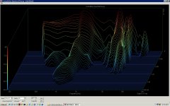
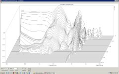
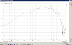
Easier to see. slightly more consistent. Easier to draw come conclusions.
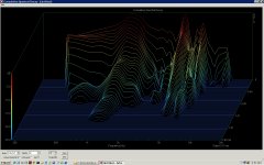
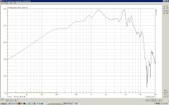
Phase plug helped the bottom end a lot. Note, the cone is also doped on this one requiring about a 50% larger box for the same bass performance. If doing an AV/sub setup, not a problem. If a stand-alone monitor, yea.
Cap mod did not as much for frequency response ( another day curing?) but did wonders for decay times.
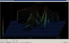
Raw driver rings till the cows come home.
From just this, the doped phase plug with a notch at 3635Hz would be a good bet. More to do. I thought the 900Hz hump was mostly baffle, but not so. I need to investigate it.
Thanks for the prod. More learned, more to learn.
Phase plug helped the bottom end a lot. Note, the cone is also doped on this one requiring about a 50% larger box for the same bass performance. If doing an AV/sub setup, not a problem. If a stand-alone monitor, yea.
Cap mod did not as much for frequency response ( another day curing?) but did wonders for decay times.
Raw driver rings till the cows come home.
From just this, the doped phase plug with a notch at 3635Hz would be a good bet. More to do. I thought the 900Hz hump was mostly baffle, but not so. I need to investigate it.
Thanks for the prod. More learned, more to learn.
Attachments
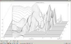
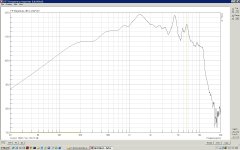
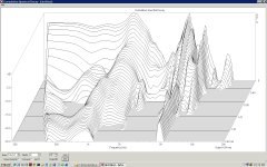
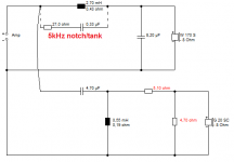
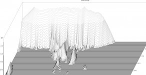
A driver that "rings like a bell around 5kHz" really shouldn't intimidate a good crossover person. Looking at your waterfall plots, it is interesting that the raw driver actually stores energy at a typical 5kHz rather than the 4.5kHz that the frequency response indicates.
It seems a bit misguided to try and outdo Silver Flute on the dustcap. I believe most good driver designers try and make drivers that are easy to filter and line up with tweeters as much as anything.
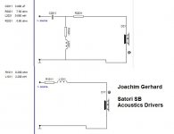
I really can't see much better than the simple left hand filter for the simple raw driver. Joachim Gerhard goes for this right hand filter for the extended frequency response SB Satori driver. Which may be where you are heading with your mods, but I think even Joachim concedes that Jeff Bagby did a better job in time aligning on a sloped baffle with his Satori take.
It seems a bit misguided to try and outdo Silver Flute on the dustcap. I believe most good driver designers try and make drivers that are easy to filter and line up with tweeters as much as anything.
I really can't see much better than the simple left hand filter for the simple raw driver. Joachim Gerhard goes for this right hand filter for the extended frequency response SB Satori driver. Which may be where you are heading with your mods, but I think even Joachim concedes that Jeff Bagby did a better job in time aligning on a sloped baffle with his Satori take.
Attachments
Steve,
I guess I don't have confidence that level effort was put into a $30 woofer. If they had, it would be a $40 woofer and would be "OK for the price" rather than the budget value leader. Then I'd expect a copper shunt and it would be a $50 woofer.
Looking at the waterfall and listening to the drivers sitting on the chair, the phase plug one is FAR smoother. I played them through my DCX with a 2.5K 4th order LP and the conclusions are the same. I made a matching plug today for the second speaker. My sim looks pretty good. Actually to get much better it winds up like the old LS3-5a with a dozen parts and 6 dB less efficiency. Not a budget build. Scope: Do better cheaper.
For those who really want to see what we are talking about, http://www.tfwm.com/newsletter_31008lesson B&W also has some nice animation on breakup modes too.
I will have a stock driver when I am done, so I'll build the tank as a test to compare them. Which cheap solution sounds better? I am not bothering with the slit version. It is better and it is easy, but it is a half way. I wish the plug helped the overall eq a bit more, but not to be.
Adding up the cost of a painted finish on PB or MDF, vs poly on wood, I think it is actually cheaper to build them of 3/4 oak. I will go ahead and make them a little larger to get a bit more bass out of them for full range use. The 14L box is fine for AV. Weak for stand alone. I have not made a hardwood box in many years, so figuring out the bracing and resonance will be a new task. I had MDF down pretty routine. I'll measure the test box sloped a bit to see if that further helps the treble. If so, then a sloped baffle it is. That will make my diffuser I put behind woofers easier.
You are now pushing up on my dream: the set of Santori's! Man do I want to try a pair. With the two gentlemen who put out the designs, I would likely build one as specked before I tried to do better. Just as John's design for the SR71 was an informative place to start. It did not take much to advance it to my preferences. (minor box changes, the aluminum rather than soft tweet, and the thin felt doughnut. After much work, the crossover converged right back to where John did it the first time.) I do have to say, I do not care for the SB tweeter the Santori is based on, but Joachim's description tells me I should shut up and try it. I really want to try a Trans Lab tweeter in something. Never heard about anyone who has.
In the mean time, I am seeing how good I can make these cheap drivers work. You have provided the only actual alternative recommendation, so I will build it. I was hoping for a few others to chime in with rational alternatives. Maybe with the constraints I set, (cheaper/better) the designs all converge. We all knew the crossover point was too low. We all knew about the breakup. Where is Planet10 with an alternative cone management plan? I keep twiddling with PSD, shifting the crossover a bit, playing with the Q a bit, and it always converges back to here unless I add a lot of parts.
Getting much closer. Getting much better.
- Tilting the baffle for the other 10mm or so offset made no determinable difference.
- Testing showed what I was afraid of, much larger coil on the woofer was needed. 5.1mH seems to be about right. Efficiency down again.
- A smaller parallel resister on the tweeter and bypass the series resister with 2 uF for a little "air". I don't really like this as it drops the impedance at higher frequencies. I may have to add a input series resister and re-do the L-pad. Listening may say if I need the cap or not.
- Did some quick listening. A monumental difference.
I can build the real boxes, as large as I can tolerate them. Order yet more coils and be into final voicing by ear with a pair.
Took the prototype out in the free space of the yard on a pole for a more boundary-free measurement of the box alignment. Got the 14L box tuned with a Qts of 1.0 and Fs of 60 Hz. About 1 dB ripple which helps the woofer trailing off a little. The good news is I was able to reduce the BSC back to close to calculation, 3.3 mH. Measuring the prototype Q with WooferTester and then plugging the Fb into WinISD got me to the measured result closer than their model from T/S parameters did.
I have lots of conclusions at this mid point:
Driver modifications were highly successful. For this driver, the dust cap was the biggest offender. I am not that surprised if you read what ScanSpeak, Fostek, Fountek, and Seas all say about dist cap issues. Planet 10 seems to take great care with them too. With the driver resting in a soft chair, full range, the difference is astounding. CSD is vastly better. Most of the harshness is gone. In hind sight, I might have tried slitting the cone with the thin silicone strips as ScanSpeak does rather than an overall coating. The real conclusion of course is to buy a better driver.
The wave guide works, but is not a help in this design. The efficiency boost is at too low a frequency. Easy as I did not need to deal with it in the crossover. So the only advantage is in getting much closer to the woofer and looking pretty cool. It also has about half the notch above 10K as the tweeter on a standard baffle, so I will keep it. I found no additional advantage of further offset of the tweeter than the 3/4 inch the wave guide provided. The real conclusion is the same as the woofer. Buy a better one.
My in-office measurements get me close enough to build a prototype. The extra space in the garage helps, but is useless below 300 Hz. Moving outside gets me what I believe will be close enough to build the pair and start critical listening. HOLM remains the most predictable to what I hear across my tool kit.
Analysis of total cost to build and finish a cabinet points me to use solid wood. Cheap wood, but solid. The materials to do a paint finish are way higher than enough poly varnish and some oak or aspen planks.
I realized to day I made a bit of an error in approach to padding the tweeter. By the low value parallel resistor, the impedance of the system remains low, but mostly restive through the top end. This is not good for power amps that would much prefer a higher impedance. They have no issue with rising inductive loads. Actually, we would all be better off if we had 16 Ohm speakers. Output stage distortion would drop significantly. I'll rework it adding an input series resistor.
Well, here is what is wrong with 5/8 particle board. I verified with a knuckle test, all the artifacts at 500-ish and 1k-ish are the sides and top.
Guess MDF is next. The heavy cone doping did wonders for breakup, but it is causing a Vb issue. The little 14L boxes are fine if stuffed, I can get a .7 Q sealed @80 Hz, great for HT, but they have more ripple than I want if I target a 60Hz ported. Not sure yet how much larger I will make them. Double would not hurt. A floor standing tower would be perfect.
Where is my picture?
- Status
- This old topic is closed. If you want to reopen this topic, contact a moderator using the "Report Post" button.
- Home
- Loudspeakers
- Multi-Way
- Budget build results, SF-Dayton