I'll have to think about that. Hard without a picture.I was tyrying to do the system, which is definately not the same vertically and horizontally. Now, if I were doing the (symmetrical) horn alone, I could simply imagine the circular wavefront and weight according to the height of a vertical chord which intersects the point between the source and the mic...then square it.
This looks like a lot of sampling around the front. Thats good for a frontal averaged response but not really a power response. For power response you have to average the whole sphere around the system. Any number of measurement points that sufficiently samples is fine, and you can always weight each measurement by the area it represents, but life gets easier if you find a regular pattern of equal areas to create a sphere.For the whole system I guess I could do a quasi thing, like the attached image.
I would suggest you go get a soccer ball and stare at its surface for a while. Imagine expanding this until it is a sphere surrounding your system. Imagine a microphone at the center of each panel that makes the ball's surface. (Okay, I realize they are made up of pentagons and hexagons, work with me here.) You want a sampling approach like that.
The whole processing would be:Once I average should I root then convert back to dB?
Convert to pressure = 10 raised by (dB/20)
Square and multiply times percentage of spherical area that measurement represents:
= p sqrd x (A/At)
Sum all powers (intensities, actually)
Convert back to dB:
10 x log of sum (10 log, since we have already squared the measurements)
Can somebody check my math on this?
Let us see some results when you get them.
David S.
Sphere from 12 pentagons: The Mathematical Tourist: Hexagons, Pentagons, and Geodesic Domes
Solids from regular polygons: Platonic Solids
Regular convex polygons: Triangles, Squares, Pentagons
David S.
Solids from regular polygons: Platonic Solids
Regular convex polygons: Triangles, Squares, Pentagons
David S.
You said...Horizontal slices of equal angle don't represent equal areas. First, are your vertical and horizontal responses the same?I'll have to think about that. Hard without a picture.
I thought...(on vertical and off horizontal) the height of a chord may be directly proportional to pressure around a lattitude line that the single measurement falls on. This is assuming the wavefront is of equal pressure over its surface.
It is nothing more than what I first thought at the time.
Attachments
Let us see some results when you get them.
I used the six horizontal plots I had, and added some power response points using your suggestion. This is a system that is crossed and working for me at around 25 degrees off axis.
I gave equal weight to each plot but half to the on axis (green) one as I counted each other twice for left and right.
This is enlightening as it doesn't seem that my horn is in fact CD.
Attachments
I used the six horizontal plots I had, and added some power response points using your suggestion. This is a system that is crossed and working for me at around 25 degrees off axis.
I gave equal weight to each plot but half to the on axis (green) one as I counted each other twice for left and right.
This is enlightening as it doesn't seem that my horn is in fact CD.
Okay, so I take it that your crosses are 1/2 Octave calculated powers from the collection of curves.
Actually that looks pretty plasuible to me. The only way to prove out something like this is to calculate for a known case, but your points are in the midst of the off axis curves and seem to have a likely shape.
You appear to be fairly close to CD. CD would mean that the power response curve and the on axis curve are parallel, i.e. have a constant dB difference. The difference in dB is the directivity index which also equals 10 x log of Q.
Subtract the two curves (axial curve minus "power" curve) and, congratulations, you've calculated d.i.! Do you have an advertised d.i. for the horn?
David S.
Hmmm, now that I look at it it doesn't look like enough directivity (2-3dB at the low end 4-5 at top). Are you weighting in enough for the off axis curves? At the very least a single backside curve which had 50% of the weighting would be required. Better would be using one of the geometric equal area approaches.
David S.
David S.
You said...Horizontal slices of equal angle don't represent equal areas. First, are your vertical and horizontal responses the same?
I thought...(on vertical and off horizontal) the height of a chord may be directly proportional to pressure around a lattitude line that the single measurement falls on. This is assuming the wavefront is of equal pressure over its surface.
It is nothing more than what I first thought at the time.
I was thinking something like this: Math Forum: Ask Dr. Math FAQ: Sphere Formulas
The second example shows the surface area of a ring of the sphere = 2 pi x r x h. h is the vertical height of each ring (vertical dimension only). If the speaker were laying on its back you might slice the sphere into 8 equal height rings (4 above and 4 below). That would include a top and bottom circular cap and 6 rings. All would have equal area and could be represented with a single response curve.
In your case, since horizontal and vertical response are different (at least in the crossover region, otherwise ignore) then you can take each of the rings and split it into 4 parts for 2 horizontal and 2 vertical measurements. This would take 26 measurements. Assume left right symmetry and you could make that 20 measurements. Cheat a little on the back side and get by with 14 measurements.
David S.
If we are going to continue this discussion of measuring the Power Reponse and DI, both of which are critical to know IMO, then we have to start to talk about precision. If all one is interested in is a rough rough calculation then just measure the axial response and convert it to power assuming a monopole. But yes thats so coarse as to be pretty much useless. Add a few more points and it gets better, but not much.
So the question then becomes to what resolution do I want from these measures and how do I know what to measure and where to get the resolution that I need? Well that question folks is a whole lot more complicated and far far beyond what one could explain in a thread like this.
I have been working on this problem for a couple of years now and I have worked out the details. An example of the results can be seen on my website if you look at Geddes Loudspeaker under the link (about half way down) Polar Data Program. In the top plot you will see the power response in red and the DI relative to the current angle in black. These are extremely high resolution data examples, about 1/20 octave.
The reference program uses a very complex data analysis done in MathCAD which was very cumbersome to use - not at all "ready for prime time". I now have a functional VB.Net program that takes HolmImpulse data and calculates the exact same data plots as shown in the referenced program (it is actually far more accurate than the older MathCAD approach).
The future of what I am doing is unclear. My intent is to write up an AES paper on the topic since it is not widely understood. But I also intended to be a bilionaire at this point as well, so not everything that one would like to do happens.
So the question then becomes to what resolution do I want from these measures and how do I know what to measure and where to get the resolution that I need? Well that question folks is a whole lot more complicated and far far beyond what one could explain in a thread like this.
Hi Earl,
I couldn't begin to tackle this on a theoretical basis as you could, but my impression has been that it wasn't that hard to get a fairly accurate power average. As long as you don't miss the primary energy lobes the average of an increasing number of spatial points pretty quickly converges on the ultimate curve. Is that not the case?
But I also intended to be a billionaire at this point as well, so not everything that one would like to do happens.
I gave up on that when I became a speaker designer!
David
Hi Earl,
As long as you don't miss the primary energy lobes the average of an increasing number of spatial points pretty quickly converges on the ultimate curve. Is that not the case?
David
Its not guaranteed, although it is often the case. IF you have a nice well behaved system then it is a lot easier to get the power response than if it is a polar mess. The point is that this is precisely what you are trying to determine. So if you assume that the speaker is well behaved then you have just pressumed the answer anyways.
There are several examples on my site and I'd have to say that, in general, the polar response is not well behaved, meaning that the power response taken from a few data points is generally not going to be very accurate.
That said, any attempt at getting power response is better than not bothering.
Dear Earl,
Sony SS-GR1:
‚r‚r-‚f‚q‚P
Did they use your first papers on waveguides - interesting coincidence.
Sony SS-GR1:
‚r‚r-‚f‚q‚P
Did they use your first papers on waveguides - interesting coincidence.
Based on that simple power response, I filled the hole at 2-3k, added one at 4k, and rolled off the top end a little. Clarity and overall balance are improved. Presence is up whilst sibilance is down.gedlee said:any attempt at getting power response is better than not bothering.
I'm actually thinking of trying HolmImpulse. I can already gate, but I'm hoping this will lend itself to more useful measurements.Allen, can you gate the measurement?
I could use VB to do the same calcs that I just did as long as the HolmImpulse data didn't need to be FFT'd. I'd see high resolution, combine as many plots as I wanted, implement weighting factors etc.gedlee said:I now have a functional VB.Net program that takes HolmImpulse data and calculates <snip>
It is tools like these that make data really useful.
I now have a functional VB.Net program that takes HolmImpulse data and calculates the exact same data plots as shown in the referenced program (it is actually far more accurate than the older MathCAD approach).
Very interesting! Hope it will be available soon!
Do you have an advertised d.i. for the horn?
It's semi DIY. Best I could do is describe it with pictures, if interested.
It's semi DIY. Best I could do is describe it with pictures, if interested.
Most horns have a directivity index (d.i.) around 8 to 10 dB. that means your calculated power curve would be 8 to 10 lower than the on-axis curve. Since your calculated curve was only 2 to 5 dB lower I am guessing you haven't done your area weighting correctly yet.
Comparing to a manufacturers spec on d.i. was just a way of checking on your results.
David S.
Viewing HOMs?
This may be a bit premature, as I'm not sure I'm seeing what I'm trying for. I made a "particle velocity microphone" by removing the back from a miniature electret microphone (the usual WM62), exposing it to pressure from both sides. This gives it a directional characteristic, rejecting sounds coming in parallel with the diaphram (as a dipole is supposed to do).
I mounted this in some brass screen (for electrostatic shield) and made a (not very stable or versatile) holder for it one of those "third hand" circuit board holders. Here is a poor photo of the mic, next to a 9V battery for size (you can barely see the 6mm capsule inside the screen).
The capsule was positioned in front of a constant directivity horn (from a QSC HPR152i), first so that it faced inward toward the driver, and then rotated to achieve the deepest response null I could get. The measurements were made with a ~4msec window to avoid in-room reflections.
The idea of this is that the wanted wavefront from the guide should be spherical, which to a small enough capsule should be reasonably close to being planar. A velocity capsule (like this one is now, more or less) should reject planar waves coming at it edgewise, leaving wavefronts from HOM which will come at odd angles. Needless to say, no numerical measurements are likely from this scheme, but perhaps some comparative picture may be doable (such as evaluating foam or the effects of defects in the throat).
The frequency response from this capsule should be (and is) rising 6dB/octave up to around 20kHz, so keep that in mind in the response plots. The driver is a B&CD DE250. Notice how the mic's response flattens the mass controlled falling response of the driver!
Here are the measured responses, red is with the mic rotated for a null:
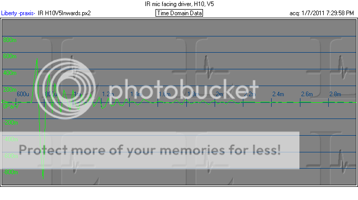
Here are the impulse responses corresponding to the responses, the direct-on response:
and the sideways-facing response:
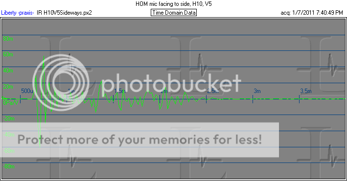
There is a lot of periodicity in the nulls of the sideways response, which might indicate interference between the direct wave and perhaps a wave reflecting back down from the mouth (?) or maybe some other reflections in the setup such as off the mic arrangement (it is all small, but will still reflect some) or something else nearby. So what is left may or not be HOMs.
To be useful, this setup would have to be made more robust, better adjustable in three planes, and testing done in a better controlled environment. But I think it might show some possibilities.
This may be a bit premature, as I'm not sure I'm seeing what I'm trying for. I made a "particle velocity microphone" by removing the back from a miniature electret microphone (the usual WM62), exposing it to pressure from both sides. This gives it a directional characteristic, rejecting sounds coming in parallel with the diaphram (as a dipole is supposed to do).
I mounted this in some brass screen (for electrostatic shield) and made a (not very stable or versatile) holder for it one of those "third hand" circuit board holders. Here is a poor photo of the mic, next to a 9V battery for size (you can barely see the 6mm capsule inside the screen).
The capsule was positioned in front of a constant directivity horn (from a QSC HPR152i), first so that it faced inward toward the driver, and then rotated to achieve the deepest response null I could get. The measurements were made with a ~4msec window to avoid in-room reflections.
The idea of this is that the wanted wavefront from the guide should be spherical, which to a small enough capsule should be reasonably close to being planar. A velocity capsule (like this one is now, more or less) should reject planar waves coming at it edgewise, leaving wavefronts from HOM which will come at odd angles. Needless to say, no numerical measurements are likely from this scheme, but perhaps some comparative picture may be doable (such as evaluating foam or the effects of defects in the throat).
The frequency response from this capsule should be (and is) rising 6dB/octave up to around 20kHz, so keep that in mind in the response plots. The driver is a B&CD DE250. Notice how the mic's response flattens the mass controlled falling response of the driver!
Here are the measured responses, red is with the mic rotated for a null:
Here are the impulse responses corresponding to the responses, the direct-on response:
and the sideways-facing response:
There is a lot of periodicity in the nulls of the sideways response, which might indicate interference between the direct wave and perhaps a wave reflecting back down from the mouth (?) or maybe some other reflections in the setup such as off the mic arrangement (it is all small, but will still reflect some) or something else nearby. So what is left may or not be HOMs.
To be useful, this setup would have to be made more robust, better adjustable in three planes, and testing done in a better controlled environment. But I think it might show some possibilities.
Last edited:
The need to change the vertical scaling (the 20+ dB level difference) is obvious, but why is the horizontal (time) axis different? Adjusting for that it would appear that the "ringing" in the throat persists *long* after the exciting impulse has passed (even worse than it looks at first glance now). If it's not "HOMs" what is it?Here are the impulse responses corresponding to the responses, the direct-on response:
The need to change the vertical scaling (the 20+ dB level difference) is obvious, but why is the horizontal (time) axis different? Adjusting for that it would appear that the "ringing" in the throat persists *long* after the exciting impulse has passed (even worse than it looks at first glance now). If it's not "HOMs" what is it?
Hmm. Just sloppiness, I was playing with the time scaling, forgot to reset them equal.
If not HOM, might be reflection off the mouth exit or from other clutter in the area, as I said this wasn't a well-controlled test. Need to do a clean setup to make sure.
An example of the results can be seen on my website if you look at Geddes Loudspeaker under the link (about half way down) Polar Data Program.
I tried to get this working on a windows 7 machine using polar_map.application and setup.exe. Are there some more files that I need to get, I noticed polar_map.manifest in the error log.
- Home
- Loudspeakers
- Multi-Way
- Geddes on Waveguides