You are confusing me ")
The guide in post #3775 doesn't mention checking across the batteries BT1 and BT (they are removed) and I can't even find the text "Briefly Check The Supply Voltages".
So you are doing the first part of the guide which is this:
Does it check out OK up to this point ?
The guide in post #3775 doesn't mention checking across the batteries BT1 and BT (they are removed) and I can't even find the text "Briefly Check The Supply Voltages".
So you are doing the first part of the guide which is this:
As faults and fault finding issues seem to crop up a lot on this amp I have put together some notes.
Fixing the O2 Headphone amp.
This guide attempts to set out a definite fault finding procedure and should cover most eventualities of non functional units. So just work through the steps measuring and checking as you go.
Checking the supplies...
The unit must first be put into a state that allows all critical voltages to be measured.
Preparation.
1) Remove ALL opamps and the comparator. Thats U1 through to U4
2) Make sure S1 is OFF.
3) Remove any batteries.
Measurement.
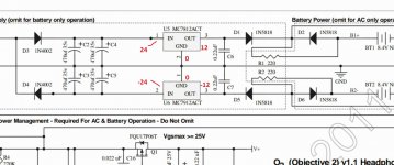
1) With your meter set to DC volts and with the BLACK meter lead firmly connected to ground (that is the common junction of C2, C3, C4 and C5 etc) measure the voltage on the striped end of D3. It should be higher than PLUS 15 volts and lower than PLUS 28 volts.
2) Keeping the BLACK lead on ground measure the DC voltage on the NON striped end of D4. It should be higher than MINUS 15 volts and lower than MINUS 28 volts.
If those conditions are OK now check the output of the two regulators. If the above readings were incorrect then you have a problem with either the AC input, a problem with the two rectifier diodes or a problem with incorrect or faulty regulators causing a short or partial short. Make sure that a 7812 is fitted for U5 and a 7912 for U6. Also make sure any electroylitics are fitted correctly with respect to polarity.
Checking the output of the regulators.
The BLACK meter lead is kept on ground unless otherwise stated.
1) Measure the DC voltage on the striped end of D1. It should be 11.5 to 12 volts approximately.
2) Measure the DC voltage on the NON striped end of D5. It should be MINUS 11.5to 12 volts DC approximately.
If you have incorrect readings for the plus and minus 12 volts yet have correct input voltages to the regulators, then the problem can only be either the regulators themselves or incorrectly fitted D1 and D5.
Does it check out OK up to this point ?
Oh well, I was doing the Initial diy testing (again) as described in NwAvGuys blog, sorry for any confusion.
As ground i used the connection from C8s minus to C9s plus, i hope thats ok!
So,"Measurement" went fine, I got respectively 24 and -24 volts.
But coming to "Checking the output of the regulators", for 1) I measured 22.5V and for 2) ca 100mV.
I am pretty sure, that I fitted D1 and D5 in correctly - striped end to striped end can not be that hard, also i got everything running once - so, the diodes are probably faulty?
Your ground point is ok 
Plus 24 and minus 24 is fine
You have a problem with the regulator outputs. Work on one at a time and check that the correct input voltage appears on the correct leg. Also make sure that the regulators are fitted correctly, the 7812 is the positive and the 7912 the negative. The pinouts are also different so look carefully at the diagram and measure all 3 pins on each regulator.
Be very careful not to short the pins when measuring.
Attachments
Your measurements suggest a problem with both regulators... which is unusual because electronic components like these are ultra reliable when used correctly.
With it in this faulty state it might be worth you switching it OFF at the mains and then checking to see there is no short between pins 1 and 3 on the 7812, and no short between pin 3 and ground of the 7912.
Beyond that and we have to say that the regulators need replacing before we can go any further.
7812 Pin: 1. Input 2. Ground 3. Output
12 resistance too high to measure
23 36kOhm
13 resistance too high to measure
7912 Pin 1. Ground 2. Input 3. Output
12 400-600kOhm (keeps changing)
23 36kOhm
13 30kOhm
Some of these measurements seem a bit unreliable to me, because they are hard to reproduce, but to answer your question, the 7812 should be fine, on the 7912 I get 33KOhm. So not a real short i guess, i could see in the datasheet what is normal.
I am probably going to order all of the static sensitive components again, they are quite cheap relative to ordering them one by one per mail.
Last edited:
Resistance reading between the above mentioned pins on the 7812. So make sure there is no short between pin 1 and pin 3. One measurement only. It will either read short circuit or not.
The 7912 was to check there was no short between the output pin and ground. One measurement again. Either a short exists or it doesn't.
If those are OK then you have to replace the regulators to prove the point.
The rest of the audio circuitry can be powered from the batteries. You can use ordinary non rechargeables to prove this... just don't attempt to charge them.
Low voltage shutdown out of spec
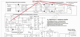
I've just completed my O2 amp. All of the tests passed except some of the resistances around the power management were slightly off and the low voltage shutdown test failed.
When removing one of the batteries whilst the amp is turned on with no headphones connected I get the following results on the L & R channels. The instructions say that these measurements should be below 0.7V but as you can see removing battery 1 produces -2.1V and takes about 1 second to drop below 0.7V ; removing battery 2 produces a larger spike to 6.7V which drops more quickly but still ~0.5s to drop below 0.7V.
Removing BT1

Removing BT2

I've tried replacing U2 and Q2 to no avail. Can anyone suggest what the problem might be, where I should look in more detail and how to fix it?
The test itself seems a bit unrealistic as there in no load attached to the output. Should it be carried out with a dummy load?
I've listened to the amp with cheap earphones and everything sounded good but don't want to plug in my expensive headphones until everything is perfect.
I've just completed my O2 amp. All of the tests passed except some of the resistances around the power management were slightly off and the low voltage shutdown test failed.
When removing one of the batteries whilst the amp is turned on with no headphones connected I get the following results on the L & R channels. The instructions say that these measurements should be below 0.7V but as you can see removing battery 1 produces -2.1V and takes about 1 second to drop below 0.7V ; removing battery 2 produces a larger spike to 6.7V which drops more quickly but still ~0.5s to drop below 0.7V.
Removing BT1
Removing BT2
I've tried replacing U2 and Q2 to no avail. Can anyone suggest what the problem might be, where I should look in more detail and how to fix it?
The test itself seems a bit unrealistic as there in no load attached to the output. Should it be carried out with a dummy load?
I've listened to the amp with cheap earphones and everything sounded good but don't want to plug in my expensive headphones until everything is perfect.
You don't need a load to check this, although a load will alter the time constant i.e. how long the supply takes to fall due to the action of the 220uF caps on each supply rail.
It sounds like yours is fine tbh. The rails can not fall to zero immediately because of the caps.
It sounds like yours is fine tbh. The rails can not fall to zero immediately because of the caps.
Completed my (first?) O2 Amp last night with a kit from Headnhifi. Everything works and it sounds great!
But! there is one small problem The left channel cuts out when adjusting the volume and I have to 'push' the volume pot up towards the top of the amp. I have to do this a few times until it 'sticks' and the left channel comes back.
What's the most likely cause of this?
But! there is one small problem The left channel cuts out when adjusting the volume and I have to 'push' the volume pot up towards the top of the amp. I have to do this a few times until it 'sticks' and the left channel comes back.
What's the most likely cause of this?
Welcome to diyAudio
This is most likely a physical problem, either something is touching and shorting to something else, or it could be a crack in the print somewhere, or it could even be the volume pot itself.
First thing to try (without wearing the headphones because it will be loud) is to short the volume control middle pin to the end pin of the control that is the input. Just hold a piece of wire to do this, don't solder anything. If the sound comes back then the control is faulty.
If not then you just have to trace the signal back which is easy. Solder a wire to the end of the appropriate cap C13 or C14 and use that to probe forward. You should have full volume audio as you work forwards towards the inputs touching the wire to the 2068 preamp chip output. If nothing there then work further toward the inputs.
There was mention of a known issue of the gain switch ??? physically touching something as I recall so check that first.
Alright, solved!
I opened it up again and pulled upwards on the volume pot. I could see a tiny metal tab on the front of the volume pot. I could have removed the pot, trimmed the tab and resoldered it but instead I just wedged a tiny piece of card in there. Bit of a dodgy fix but it does the job (I'm just surprised it works at all to be honest!)
I opened it up again and pulled upwards on the volume pot. I could see a tiny metal tab on the front of the volume pot. I could have removed the pot, trimmed the tab and resoldered it but instead I just wedged a tiny piece of card in there. Bit of a dodgy fix but it does the job
(I'm just surprised it works at all to be honest!)
Oh well, it took me some time to get the replacement voltage regulators and the time, to desolder the old ones. Oh man, that was a real pain, needed some help of a good friend of mine for that.
They are replaced now and they work correctly.
But the amplifier still does not work.
So I went ahead in your guide. In "Checking the voltage comparator and switched output rails" I don not get the correct voltages on pin 8 of U2.
I am going to order new ICs and see, if that fixes it.
They are replaced now and they work correctly.
But the amplifier still does not work.
So I went ahead in your guide. In "Checking the voltage comparator and switched output rails" I don not get the correct voltages on pin 8 of U2.
I am going to order new ICs and see, if that fixes it.
Are original gerbers still ok or there are updated in the meantime? Thanks
I have no idea on that I'm afraid. As I keep saying, I have never built, seen nor heard an 02
- Home
- Amplifiers
- Headphone Systems
- The Objective2 (O2) Headphone Amp DIY Project