Both Digikey and Mouser have them in stock.
All I see are ROHM op-amps for that part number at Mouser:
LM4565F-GE2 ROHM Semiconductor | Mouser
I typically associate a op-amp with a "LM" prefix with being made National Semiconductor, not ROHM(whoever that is).
So where is the National or TI equivalent and what's so special about it other than it's relatively high output current?
It's less-than-stellar slew rate of 5V/us certainly isn't nothing special, but at a price of only $.45 ea. it's cheap enough to try.
Last edited:
d4 measurement not ok
Hello all, i hope you can help me out.
I bought a kit from head'n'hifi, soldered everything and now i'm testing.
the voltage measurement (with ac power and only u2 installed) of the banded end of d4 should be 13.5-22.5 but it's 0. the source is 17V. the banded end of d3 is 23.7.
the non-banded end of d4 seems ok: -23.5.
the resistor measurement (in circiut) seems ok but some of the values with (*) are at their max values r4, r24=270k or greater: r2=236, r1=238.
thank you!
never mind me. i was not measuring vac. total noob here.
everything works fine - me happy.
Hello,
I have a problem with my Objective2 + ODAC combo I need some help with.
My objective 2 iteself works fine. The same goes for the ODAC.
My ODAC output pins are soldered to the Objective2 input pins as they are supposed to.
When I listen to the ODAC via the headphone input of the Objective2, everything is completely fine. But when I power on the Objective2 and listen to the headphone output (ODAC still being the source), there are several problems;
- I have to turn up the volume knob all the way up to hear at a somewhat decent volume.
- There is a significant channel imbalance
- With the volume know turned down all the way, I can still hear the lower frequencies (equally loud on both channels)
I really hope anyone can help me, I'm really running out of ideas...
Welcome to diyAudio ")
I'm a bit confused as to what is happening tbh.
You say the 02 is OK and also the ODAC.
I'm assuming that when you mention I listen to the ODAC via the headphone input of the Objective2, everything is completely fine I am taking that to mean you have headphones plugged into the 3.5mm input jack of the O2.
This is really where an oscilloscope comes into its own for faultfinding.....
Lets work with this bit first With the volume know turned down all the way, I can still hear the lower frequencies (equally loud on both channels)
If you look at the 02 circuit then you can see that the wiper (middle pin) of the volume control goes to ground when the pot is rotated to minimum. That should kill all audio.
Can you confirm that that is not happening when you listen to the 02 headphone output ?
Thanks for the fast reply.
That's what I was trying to say, yes.I'm assuming that when you mention I listen to the ODAC via the headphone input of the Objective2, everything is completely fine I am taking that to mean you have headphones plugged into the 3.5mm input jack of the O2.
That is correct. And also the reason why I'm so confused myself.If you look at the 02 circuit then you can see that the wiper (middle pin) of the volume control goes to ground when the pot is rotated to minimum. That should kill all audio.
Can you confirm that that is not happening when you listen to the 02 headphone output ?
Hmmm... its an interesting problem then
You need to look first of all at why the volume control isn't fully muting the audio.
First thing to check is:
That with the control fully anticlockwise and the O2 powered down (OFF) that there is no more than one or two ohms between the middle leg of the volume control and the ground leg next to it. It should theoretically be zero but it never is on most pots. Also confirm that the ground leg of the control has virtually zero resistance to the audio input grounds and power supply ground. It should be fractions of an ohm at most.
Any problem there will almost certainly be something physical that is wrong.
Even if the readings seem OK we still have to go one step further and now add a quick shorting link from the middle pin of the volume control (both channels) to the ground pin next to them. There has to be zero audio present now.
Measuring the resistance between the middle leg and the ground pin of the volume control resulted in 6.5 ohms and 11.2 ohms.
There's exactly 0 ohms between the volume control grounds and input ground. I wasn't exactly sure what you mean by power supply ground, but I suppose it's one of the battery-pin grounds (which would measure 0 ohms as well).
Now to the interesting part. After soldering the center and ground pins of the volume control together, I could still hear some slight signal coming out of the output.
This still only happens with the ODAC as my input source and not when connecting a source to the input jack of the O2...
Not sure what to make of that.
It looks like the pot resistance readings are probably normal for the pots used.
With the pot deliberately shorted and you still hearing audio... that is weird. And it only does that with the ODAC and not a normal line level input.
The only things I could suggest would be to look at how the ODAC grounds are connected and how the power supplies interact.
Are you running the O2 on battery for test purposes ?
Headphones are super sensitive and will give detectable audio with only a millivolt or two of signal. With the volume control pins shorted out the only thing I can think of is that some circulating audio related current is being developed across the essentially 'zero resistance' of the ground traces. That would only be possible if there were a loop and also if the ODAC had considerable 'drive ability' (which it may well have).
I'm back with some new results.
During the last days I went through all the DIY-Testing and Troubleshooting steps descibed in the O2 Details page. While all the measurements there turned out fine, I measured the Voltages across D3 and D4 with the O2 turned off just out of curiosity.
It turns out that the voltage across D3 is at 24 V and there's almost no voltage across D4.
When I turn on the power switch, both voltages are sitting at 24V.
I'm pretty sure that this could be part of the cause for my problem, but I don't really know where to look now
I doubt there is any problem around the diodes. If the two voltage rails are correct as measured at the output of the two voltage regulators then all is well there. You should have +12v on D1 and -12v on D5.
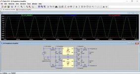
The voltages on D3 and D4 may seem odd because one end of each diode is actually connected to the AC input.
This is the same arrangement (just different regulators) and you will see the relationship of the voltages at the three points in the circuit related to those diodes. A DVM will not make much sense of what is really happening because of the AC present.
Attachments
Thanks for clearing that up Mooly.
I guess you were right, when you suspected the problem to be related to the grounds.
I've been checking the Input pins from the ODAC to the input jack pins for continuity, one time without anything plugged into the input jack and one time with some earbuds inserted (no power connected both times).
With the earbuds inserted, all the pins showed the expected behaviour, but after I removed the earbuds there was continuity from the left and right pin of the ODAC to the input Jack ground (almost 0 ohms).
This would explain why there was a slight signal even with the volume know turned all the way down only when using the ODAC.
What I'm not sure about (again...) is the source of this problem.
Could it just be that the input jack is damaged in some way?
I wouldn't like to say if it could be damaged...
Also remember that I have never even seen, let alone heard an 02, and so all the fault finding advice I have given is based purely on the published documentation
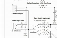
If you look at the diagram (and this is the first time I have really looked closely at this part of the diagram) of the input socket then you can see it appears to be drawn in such a way as to 'short out' the 'off board input' from P1. That is how it looks to me.
For example pin 1 of P1 goes into pin 5 of the 3.5mm socket and then directly to ground on pin 4 via the internal arrangement of the socket.
Is this what you are reading when you mention 0 ohms ?
If so, and if this is how it really is then it will short the input from P1. As a test you could try plugging a blank plug into the socket (blank meaning just a bare plug with nothing attached).
Also remember that I have never even seen, let alone heard an 02, and so all the fault finding advice I have given is based purely on the published documentation
If you look at the diagram (and this is the first time I have really looked closely at this part of the diagram) of the input socket then you can see it appears to be drawn in such a way as to 'short out' the 'off board input' from P1. That is how it looks to me.
For example pin 1 of P1 goes into pin 5 of the 3.5mm socket and then directly to ground on pin 4 via the internal arrangement of the socket.
Is this what you are reading when you mention 0 ohms ?
If so, and if this is how it really is then it will short the input from P1. As a test you could try plugging a blank plug into the socket (blank meaning just a bare plug with nothing attached).
Attachments
Wow, you're right!
Having a blank plug in the input socket solves the problem.
I guess I was staring at the diagramm for so long I just ignored the shorts to ground at the input plug...
After some more research I just found another blog post by NwAvGuy in which he recommends cutting the traces to ground on the PCB.
I guess that marks my problem as solved
Thanks for the being such a great help Mooly
Excellent
So that confirm that it is a slightly odd design for this situation to occur. If you are never going to use the socket then cutting traces or simply removing the part would be a good fix.
If you do cut traces then you need to be sure you do it right because it would be easy (depending on the board layout) to end up with either pin 3 of the wanted input being cut or slightly more unusual, ending up with pins 2 and 3 effectively shorted out.
- Home
- Amplifiers
- Headphone Systems
- The Objective2 (O2) Headphone Amp DIY Project