O dear, Carl  !
!
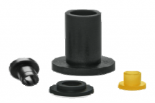
As I wrote on page 35 of my "Builder's Manual": move a MICA washer or silicone thermal conductive foil between the transistors' backs and the ALU-L profile.
Insulate the srews by means of "shoulder washers (? - see attached image) or polyamide screws and verify after soldering that all of the legs of all transistors
have infinite resistance to the ALU profile.
I hope that the BD139 was the only part that you fried.
I wish you good luck - Rudi_Ratlos
!As I wrote on page 35 of my "Builder's Manual": move a MICA washer or silicone thermal conductive foil between the transistors' backs and the ALU-L profile.
Insulate the srews by means of "shoulder washers (? - see attached image) or polyamide screws and verify after soldering that all of the legs of all transistors
have infinite resistance to the ALU profile.
I hope that the BD139 was the only part that you fried.
I wish you good luck - Rudi_Ratlos
Attachments
Carl, before you risk the remaining BD139:
Measure the resistance between all transistors' legs and the ALU-profile! Your DMM should read: infinite resistance!
Do not insert fuses into the on-board fuse-holders, but bypass them by a small 0.25W / 10 Ohm resistor!
This is the recommended procedure (documented in the builder's manual)!
An error like you did would have blown the 10Ohm resistor and not any precious transistor!
And please: use a bulb-tester as well!
Best regards - Rudi
I used my DMM in diode test mode on all transistors on board. The bad board reads EXACTLY the same as the good board...
This is most frustrating
All caps are correct.
There are no apparent shorts
Transistors all read the same via the quick transistor test.
I dont know what to do...
both rails still get 800+ mV upon startup immediately. Something is letting all that voltage through...I am still suspect of a bad BD139 since it is common to both rails...it must be something like that that is common.
Carl, can I help you in any way?
If the relay on the speaker protection PCB is not engaging: one possible reason is that there is >1V DC on the speaker's output (I assume, this is the reason why).
I finished the SYMASYM for my brother yesterday night.
It is playing beautifully.
Best regards - Rudi_Ratlos
If the relay on the speaker protection PCB is not engaging: one possible reason is that there is >1V DC on the speaker's output (I assume, this is the reason why).
I finished the SYMASYM for my brother yesterday night.
It is playing beautifully.
Best regards - Rudi_Ratlos
Attachments
OK so I ordered a few replacement bits from mouser...I will attempt to get the other channel running this weekend.
One question...on the speaker protect is it really one leg of the A/C to the upper pin and a ground to the lower pin? I am not following that logic. I hooked up A/C to both pins an fear if that is not correct then I might have fried one or more of the ic's.
If you look at the connection diagram in the manual both legs come from the ground of the psu board.
Last edited:
vs FC-100?
Hello Rudi
Been following your threads on the TO-3 Symasym and also the FC-100. Now you've built the TO-3, I'm interested to know - which amp do you prefer or do they both have different strengths?
Thanks
Hello Rudi
Been following your threads on the TO-3 Symasym and also the FC-100. Now you've built the TO-3, I'm interested to know - which amp do you prefer or do they both have different strengths?
Thanks
Carl, can I help you in any way?
If the relay on the speaker protection PCB is not engaging: one possible reason is that there is >1V DC on the speaker's output (I assume, this is the reason why).
I finished the SYMASYM for my brother yesterday night.
It is playing beautifully.
Best regards - Rudi_Ratlos
So I replaced the bd139 and have eliminated the runaway but now I can only get the 0281 side to bias up. I get it to 25mV and the 0302 side goes to about -240mV. The sides are out of balance. I also replaced the mje's which made no difference.
I am getting close to throwing in the towel on this one.
Looking at the schematic the next possible culprits are the 5551's or possibly the 5401's.
Any other ideas are appreciated.
Also I don't think anyone answered my a/c hookup question for the speaker bords.
I am getting close to throwing in the towel on this one.
Looking at the schematic the next possible culprits are the 5551's or possibly the 5401's.
Any other ideas are appreciated.
Also I don't think anyone answered my a/c hookup question for the speaker bords.
Carl, the procedure to set the quiescent current / bias of the SYSMASYM is as follows: preset the potentiometer to 500Ohm and connect your DMM to MP1 and MP2
(you will then measure the voltage drop across 2 adjacent emitter resistors). Do not connect a speaker to the output and put a short across the input (Input + = INPUT -).
Turn power on. The display of your DMM should read 0mV. Turn the potentiometer counter-clockwise and tell me, if you can adjust the SYMASYM so that the DMM shows about 24mV.
The value of 24mV means that about 60mA is flowing through each of the 0R22 emitter resistors.
What question do you have about connection the speaker-protection PCB?
Carl: you would be the 1st of several hundreds (!) of DIYers, who is not able to finish the SYMASYM!
Best regards - Rudi
Yes I did that but the 0302 side is getting too much current. I can get the 0281 side to bias to 25 mA.
I suspect the 0551's are letting too much current through.
follow Andrews advice and post the results.
Do the speaker protect boards get 2 legs of a/c or one leg and one earth ground?
I suspect the 0551's are letting too much current through.
follow Andrews advice and post the results.
Do the speaker protect boards get 2 legs of a/c or one leg and one earth ground?
Cj,
let's try to understand what your output should be doing, then you might be able to see what is going wrong.
1.) look at the output node.
2.) draw each connection from that node.
3.a) one goes up to Nch
3.b) one goes down to Pch
3.c) one goes to Zobel
3.d) one goes to NFB
3.e) one goes to speaker
4.) discount those that cannot pass DC during set up
That removes the speaker (it is not connected), and removes the Zobel (it has a capacitor)
5.) Look at DC current passing through the last 3 remaining connections.
Idle bias comes in through Nch, idle bias goes out through Pch, error current passes out via NFB.
6.) How big is that error current into the NFB. Assume the output offset is enormous @ 10Vdc and that the NFB upper leg resistor is 33k. The NFB error current would be 0.3mA
As output offset reduces then the error current reduces in direct proportion. I will suggest you ignore it. (first check what value of NFB upper leg resistor is actually fitted?)
7.) there are ONLY two connections that can conduct (significant) DC current at that output node: the Nch feeding in and the Pch sinking out.
These two currents must be equal. They cannot be high in one half and low in the other half.
There is something wrong with what you have posted
What are you doing wrong?
let's try to understand what your output should be doing, then you might be able to see what is going wrong.
1.) look at the output node.
2.) draw each connection from that node.
3.a) one goes up to Nch
3.b) one goes down to Pch
3.c) one goes to Zobel
3.d) one goes to NFB
3.e) one goes to speaker
4.) discount those that cannot pass DC during set up
That removes the speaker (it is not connected), and removes the Zobel (it has a capacitor)
5.) Look at DC current passing through the last 3 remaining connections.
Idle bias comes in through Nch, idle bias goes out through Pch, error current passes out via NFB.
6.) How big is that error current into the NFB. Assume the output offset is enormous @ 10Vdc and that the NFB upper leg resistor is 33k. The NFB error current would be 0.3mA
As output offset reduces then the error current reduces in direct proportion. I will suggest you ignore it. (first check what value of NFB upper leg resistor is actually fitted?)
7.) there are ONLY two connections that can conduct (significant) DC current at that output node: the Nch feeding in and the Pch sinking out.
These two currents must be equal. They cannot be high in one half and low in the other half.
There is something wrong with what you have posted
This cannot happen during the set up procedure !!!!the 0302 side is getting too much current. I can get the 0281 side to bias to 25 mA.
What are you doing wrong?
OK
On the bad channel
With the pot to 500 ohms.
No voltage across any of the 4 emitter resistors
-57 mV present at speaker output
Both measuring points indicate -57 mV
Now
I bias until MP1 reads stable 24mV
Each source resistor is dropping about 83mV plus or minus
MP2 reads -142mV
Still -57mV present at the speaker output
The -57mV is getting introduced from R7 C9 and can be traced back to the middle pin of Q2. This is different than the other channel which reads 3.8mV.
The 170s are both verified good via dmm diode test. R29 and R39 are both dropping approx 31.5mV.
So where is this -57mV coming from? I am stumped.
mV is voltage,
mA is current.
Are you getting some of your reports mixed up?
All of post559 shows voltage.
post556 is talking about current.
post the voltage measurements on the schematic. Add in many more measurements so we can see the voltage differences across components.
mA is current.
Are you getting some of your reports mixed up?
All of post559 shows voltage.
post556 is talking about current.
post the voltage measurements on the schematic. Add in many more measurements so we can see the voltage differences across components.
You are correct...I was assuming the more negative measurements on the 0302 side from the MP meant that it was drawing more current but I was wrong. They are all conducting the same but somehow something is passing negative DC to the speaker output and it must be something connected to the feedback.
- Home
- Group Buys
- TO-3 SYMASYM