Carl, do not yet give up! We (!) will do our best to enable you to fix the error.
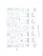
Find attached a picture with the currents flowing, when you do the adjustment of the SYMASYM. But I wonder, if the image will help you.
Please tell me, what you did wrong.
I know from your post that you forget to isolate the back of the BD139 TEMPCO transistor. But his cannot be the only error.
Did you also forget to put "shoulder washers" beneath the screws of the drivers (MJE15030/MJE15031)?
Best regards - Rudi
Attachments
BTW,
that marked up diagram shows two very useful bits of info.
1.) 1.225uA flowing into the bases of both input transistors. That combined with the 22k resistors gives identical voltage drops across these resistors. If the other ends of these resistors are at Zero Volts, then the bases of the input transistors MUST be at the same voltage.
2.) The currents in the input collectors and in the input emitters and in the input bases are all identical to their partners. This is the ideal you want when setting up your amplifier. If you have selected your 680r and your two input transistors well, then the Zero Volts from 1.) must ensure you have virtually 0.0mVdc of output offset.
A small error in Vbe between the two input transistors will result in a small error in output offset, if you have ensured that all the currents are equal as shown in the schematic.
And could someone please clarify how to hook up the A/C to the speaker protection circuit?
The text, diagrams, and instructions all seem to say something different.
Do I hook up one of the complete secondary windings to the A/C input or just one leg of A/C and one to earth ground?
The text, diagrams, and instructions all seem to say something different.
Do I hook up one of the complete secondary windings to the A/C input or just one leg of A/C and one to earth ground?
OK...with the amp terminal not connected on both channels the speaker protect works on both channels. For both channels, as soon as the amp terminal is connected the LED's shut off and the relays click closed.
The good channel has ~1mV
The bad channel has -57mV
One thing...I do measure about 16VAC on the amp terminal of the speaker protect boards
I am beginning to think this amp HATES me.
The good channel has ~1mV
The bad channel has -57mV
One thing...I do measure about 16VAC on the amp terminal of the speaker protect boards
I am beginning to think this amp HATES me.
Dear Carl,
I think your board does not have any big issues. Each emitter resistor have 70mv accross it.That means current through them(and ofcourse through output transistors also) are approx 320 ma and are equal.So the biasing of the transistors are okay.This current is little higher than the required quiescent current.You can reduce it using the preset.But the output have some offset towards negetive side.This may due to feeback circuit or mismatch of input diffrential stage.which transistor you are using BJT or JFET ? To identify this , you swap the transistors Q1 and Q2.If the offset goes towars other side,ie towards +50mV,you replace these devices with matched one.Otherwise you please check the following components and their wiring. R2,R3,R6,R7,R11,C3,C4 etc.Could you post the collector,emitter,base voltages of Q1 and Q2
with regards
joshvi
Last edited:
AC or DC?..............The good channel has ~1mV
The bad channel has -57mV
Oscillation? Was this always present and you just forgot to tell us?One thing...I do measure about 16VAC on the amp terminal of the speaker protect boards
OK - I am listening but decided to step back, spend another $15 at mouser and replace all the transistors just to rule that out. I figured that was a small price to pay for sanity.
I should have everything re-stuffed in the board this weekend.
Thanks again for the help!
In the meantime, however, any thoughts on why I am getting 16VAC on the amp terminal of the speaker protect boards?
I should have everything re-stuffed in the board this weekend.
Thanks again for the help!
In the meantime, however, any thoughts on why I am getting 16VAC on the amp terminal of the speaker protect boards?
Carl, the AMP-terminal of a speaker protect PCB is connected to a speaker-output terminal of the SYMASYM PCB.
Does your question mean that you have 16VAC on the speaker output terminal while adjusting the quiescent current /BIAS?
Best regards - Rudi_Ratlos
Does your question mean that you have 16VAC on the speaker output terminal while adjusting the quiescent current /BIAS?
Best regards - Rudi_Ratlos
OK - I am listening but decided to step back, spend another $15 at mouser and replace all the transistors just to rule that out. I figured that was a small price to pay for sanity.
I should have everything re-stuffed in the board this weekend.
Thanks again for the help!
In the meantime, however, any thoughts on why I am getting 16VAC on the amp terminal of the speaker protect boards?
- Home
- Group Buys
- TO-3 SYMASYM