")
Peter,
Your PS board looks like it has more parts than my previous CRC power supply.
http://www.diyaudio.com/forums/showthread.php?t=140306 post #4.
The green board in #9 looks more liike what I used on my first F5.
I downloaded the Excel sheet with the BOM for the amp board and PS.
If I order the parts for the PS as listed in the BOM, will I have everything I need? Any jumpers required on your PS?
Still waiting for the boards, but would like to place an order today for all other parts.
Thanks,
Vince
My official PS board was described here: http://www.diyaudio.com/forums/showthread.php?t=149672
Should still be good. $37 for the transformer and $10 flat rate shipping, total $47.Um...that's funny. The AN-4218 on their new site is $44. Paid $47 with the group buy.
Did the price of copper go down?
Either way, it's a good price and it's a nice transfo. No complaints here.
V~
Yes, I have plenty of boards available, ordering info was posted on a first page.
I also have matching PS boards in stock: http://www.diyaudio.com/forums/showthread.php?t=149672
I also have matching PS boards in stock: http://www.diyaudio.com/forums/showthread.php?t=149672
Yes, I have plenty of boards available, ordering info was posted on a first page.
I also have matching PS boards in stock: http://www.diyaudio.com/forums/showthread.php?t=149672
Ok, so for a stereo amp I need the F-5 board, which I understand is both channels, and the power supply board, now do I need the complete 30 dollar board, or do I need 2 of these? ( again for a stereo amp, not monos)
Thanks for your time,
Russellc
I'm just a little confused as to which power supply board I need, The F5 needs the dual positive rather than the symmetrical one?Indeed, a stereo set of F5 amp board (2 channels) is $15 and you only need dual positive section of PS board (at $20); one should be enough for stereo.
Total comes to $35, shipping included.
In this way, I'm having either a symmetrical amp PS pcb (good for F4, F5, AJ-X amps) or dual positive supply (F2, F3).
Thanks again for your patience!
Russellc
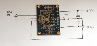
f5 gounding scheme
Peter
Awhile back,discussion, and occasional confusion, ensued over proper grounding with your boards. You stated that you supplied a pad with two locations for ground. One hole for the incoming signal and one for connection to the PS ground located between the caps where you suggested the speaker ground should also be located. I have built three sets of amps with your boards and on all of them I have used the cap/speaker ground as the location for my input/output ground and have a very low noise level , no turn on thumpage generally well behaved little puppies. It essentially looks like a professional star ground design.
I also have eschewed the current limiting and thrymistors and followed NP's suggested feedback modification and your suggestion to biamp instead of bridge. I am using barrolboss's large heat sinks oriented vertically(10"w x12" h) and they do run hotter than my fan cooled version , typically40-45 degrees faranheit over ambient temp after one hour of power-up. I am now two months into the listening and am quite pleased. They do sound better after 30 minutes or so, I believe the bias settles at that point at around 1.15 vdc.
Just thought I'd check in and hope all is well with you
take care
rob
I have built three sets of amps with your boards and on all of them I have used the cap/speaker ground as the location for my input/output ground and have a very low noise level , no turn on thumpage generally well behaved little puppies. It essentially looks like a professional star ground design.
Hi Rob, The signal ground and power grounds should be separated. If you connect the input ground directly to "cap/speaker" ground, that could be causing that low noise. The input ground should be connected to the amp board first and then to common ground on caps where speaker output ground is taken from.
Attachments
TP THERMiSTER OR NOT- WHERAST GO THOU?
hI pETER
i MOVED THE GROUND YESTERDAY AND BELIEVE i HEAR mucho better detail- thanks berry much- I heard a yawn towards the end of "I"m only sleeping"(REVOLVER) that I'd never heard before-
yeha baby this is the good stuff!
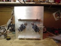
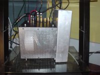
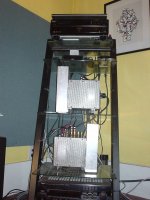
I've included some pictures for your viewing pleasure-enjoy!
My question about the thermister really had to do with bennefit vs deficit;
bennefit- more stable bias i believe was the stated purpose- this is a good thing I've monitored my amps over 4 hours and with no input(not shorted) it tends to move around quite abit (+/- .25vdc) though it tended to stablize(+/-.125) after about 1 hr( reaching a fairly stable temp around 135-140 degrees farenheit)
deficit-sonic affect of it "regulating" the voltage flowing through it? perhaps someone with a better grasp of the circuit and this component could lay out the theoretical deficit of the thermister.
I run without it and am happy with the sound of the amps but wonder if the inclusion of the thermister would help keep the bias more stable.
inquiring minds wanna know!
take care all
rob
hI pETER
i MOVED THE GROUND YESTERDAY AND BELIEVE i HEAR mucho better detail- thanks berry much- I heard a yawn towards the end of "I"m only sleeping"(REVOLVER) that I'd never heard before-
yeha baby this is the good stuff!
I've included some pictures for your viewing pleasure-enjoy!
My question about the thermister really had to do with bennefit vs deficit;
bennefit- more stable bias i believe was the stated purpose- this is a good thing I've monitored my amps over 4 hours and with no input(not shorted) it tends to move around quite abit (+/- .25vdc) though it tended to stablize(+/-.125) after about 1 hr( reaching a fairly stable temp around 135-140 degrees farenheit)
deficit-sonic affect of it "regulating" the voltage flowing through it? perhaps someone with a better grasp of the circuit and this component could lay out the theoretical deficit of the thermister.
I run without it and am happy with the sound of the amps but wonder if the inclusion of the thermister would help keep the bias more stable.
inquiring minds wanna know!
take care all
rob
Attachments
Alright, so I did some measurements today with my amps: http://www.diyaudio.com/forums/showthread.php?p=1740775
These are the bias values across 0.47R resistors while warming up (without thermistors):
0.28V right after turn on
0.4V in 5min
0.5V in 15min
0.55V in 30min
0.6V in 50min
I don't recall that much of a difference with thermistors. Some settling time was also required for bias to stabilize.
So 30min is not that bad for a warm up, basically in line with other class A amps.
- Status
- This old topic is closed. If you want to reopen this topic, contact a moderator using the "Report Post" button.
- Home
- Group Buys
- F5 pcb group buy...