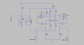
Here is part of the design I am working on currently. The bias is done differently, but the basic principle is the same.
I expect to use gains of 6dB, 16dB and 26dB.
The difference is very small, the two resistors sample the same average current of both FET's. The multiple CMRR trims look like a pain but if you want 100dB everywhere maybe necessary.
The president of SR is a nice guy, sent me a pile of datasheets noting the parts he uses (39 - 797's in one).
Last edited:
So, that's what you meant about attenuator?But we do need that CMR.
-RM
No That was something else but it didn't work.
The reason for the discussion is the need of a sacrificial front end for the AP and QA400, and an HP403B. The AP is 100k/185 pF which is too low for vacuum tubes. I will build mine out per Sams PDF with the CCS he showed in the LA article, and include the option of pre-charging the DC blocking capacitors (a la the Tektronix 7A22N diff amp).
I think you should clearly define what you need that frontend for (or you'll get random "solutions" throwed at you). I assumed you're looking for a preamp with differential input to measure very low noise sources. If the task is to do THD measurements at high-voltage tubes you need something else, probably.
Samuel
If the task is to do THD measurements at high-voltage tubes you need something else, probably.
Samuel
The 7A22 manual is a free download. How things have changed, they basicly teach you in great detail how the whole thing works.
What App?
I think from reading the lit on the QA190 probe.... it is intended to measure across the ac power line (120v). Then take FFt of the signal, etc. Here though, I dont know why high voltage measurement would be needed... unless, it was tube electronics. [but low very low noise wouldnt be needed?]
Maybe for bridged power amp output measurements?
THx-RNMarsh
Last edited:
I think you should clearly define what you need that frontend for (or you'll get random "solutions" throwed at you). I assumed you're looking for a preamp with differential input to measure very low noise sources. If the task is to do THD measurements at high-voltage tubes you need something else, probably.
Samuel
Yes, it's noise in HV applications. I was perplexed that a couple of folks thought that the depletion MOSFET CCS was "noisy". I don't know if there's been a lot of work done characterizing them for noise.
I've built Scott's diffamp but it keeps railing.
I've built Scott's diffamp but it keeps railing.
I've built 2 or 3 without a problem. Offset problems?
I've built Scott's diffamp but it keeps railing.
Input not ref to ground return?
-RNM
Yes, it's noise in HV applications. I was perplexed that a couple of folks thought that the depletion MOSFET CCS was "noisy". I don't know if there's been a lot of work done characterizing them for noise.
I've built Scott's diffamp but it keeps railing.
it sounds to me like you have the feedback polarity swapped somewhere. It can be a bear to figure out.
I have been using depletion mode Mosfets very successfully in a number of locations. I would use it to cascode a current source since the intrinsic noise is pretty high. As a cascode its gain is very low so the noise below the source dominates. However its an easy way to get 300V of compliance from a current source.
I think you should clearly define what you need that frontend for (or you'll get random "solutions" throwed at you). I assumed you're looking for a preamp with differential input to measure very low noise sources. If the task is to do THD measurements at high-voltage tubes you need something else, probably.
Samuel
This is an important point. Jen's application is the imput of a high performance ADC for measurements. Jackinnj's application is looking inside of a tube amp. They share some aspects but have some different requirements.
To optimize the design you need to address the following:
Input noise requirements
Distortion maximum
Gain options?
Maximum common mode requirements
DC or AC coupled
Max output swing
Input impedance requirements
For jen's application I'll add some numbers to focus the task:
Input noise requirements: approx -130 dB below full output in a 20 KHz band (equal or better than the SNR of the best available ADC)
Distortion maximum: -125 dBC for any harmonics (to be better than the best available ADC)
Gain: 6, 26 and 46 dB
Maximum common mode requirements: unknown at this time? Clearly limited by the power supplies.
DC or AC coupled: Both?
Max output swing: 4V (the next stage is differential so it really should be a differential output)
Input impedance requirements: very high and very linear so the input won't introduce distortion on the output of the source if the source is not low impedance.
These are some pretty challenging design requirements.
One comment on these designs; When used with a single ended source the common mode will be 1/2 the signal level internally. This means the opamp U1a output swings at approx 1/2 the input and needs to do a pretty good job.
The 7A22 manual is a free download. How things have changed, they basicly teach you in great detail how the whole thing works.
Yes--I have two or three 7A22s and surely a printed manual. This plugin alone makes the hunt for a 7000 mainframe (just got another 7904A in excellent condition
) worth it!Look up the 7A13 for really good CMRR. The gain is lower and the noise is higher but 100 MHz and enormous CMRR. More tricks to steal.
If they just would have used good relays... I'm thinking of redesigning the circuit rather than fixing the pile of defective ones I've got. There are now amplifier topologies with much faster overload recovery (see Addis work for the Tek 11000 series).
Samuel
Yes, it's noise in HV applications.
I have not studied tube circuits--I presume the expected noise voltage is one to two orders of magnitude higher than for (very) good transistor design? So I'd say a noise floor of around 10 nV/rtHz should do the trick. Also I'd suggest you stay with unity gain. This will not mess with the calibration of the AP you have, and make interpretation of the measurement data very simple.
So it looks to me as if two OPA827 connected as buffers, with a suitable AC coupling and protection network at the input, is all you need. If a bit higher noise floor is acceptable, even a TL072 will fit.
Samuel
I've built 2 or 3 without a problem. Offset problems?
Sorry I didn't think of it till this morning, but the common mode op-amp needs a common mode range near the plus rail. The SR circuit less so for the same result (but two more matched resistors). When I reduced the resistor values and voltage drops the op-amp is marginal unless it works .5 V from the rail, there are plenty of choices these days but it is easy to overlook.
I think from reading the lit on the QA190 probe.... it is intended to measure across the ac power line (120v). Then take FFt of the signal, etc. Here though, I dont know why high voltage measurement would be needed... unless, it was tube electronics. [but low very low noise wouldnt be needed?]
Maybe for bridged power amp output measurements?
THx-RNMarsh
Anybody checked out Burkhard Vogel's 'poor man's measurement amp' in Vol 7?
Fully diff, high CMR.
Jan
Attachments
Anybody checked out Burkhard Vogel's 'poor man's measurement amp' in Vol 7?
Fully diff, high CMR.
Jan
I think we were looking for high input impedance. Full balance and CMR looks to need a lot of trims too.
Last edited:
- Home
- Design & Build
- Equipment & Tools
- Differential take on Groner's LN Measurement Amp