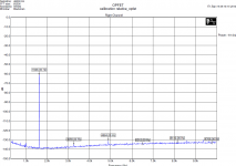
The notch is 0dB at H2 ?
Level of 1628Hz fundamental is 0dB. The notch is -60dB at 1628Hz. So you can directly read amplitudes of harmonics H2, H3 and so on, H2 needs a small correction because of notch attenuation, so the H2 would be about -130dBr. I hoped this was very simple to understand. AD797, ADA4898 and others.
You can make it better of course, if you like, but then come with results and not with the chat.
Yes, I was rather sad when I found out too. Some very serious knowledge walked out the door with Scott and I just genuinely liked the guy. Thankfully he left rather a lot scattered around the forum too. It is sad we wont be seeing anything new from him here though"Why the tears?"
See post #60.
Patrick

Thank you all for the suggestions!
EUVL - your solution is very much what I was hoping for! Thank you very much!
A follow-up question - Scott mentioned that an OP with 4-6 nV/sqrt(Hz) voltage noise would be required to take fully utilize the low noise of circuit. However, if the U1 AD820 in your simulation model is swapped for an LT1678 or ADA4625, the amplifier output gets an offset of around 9.3 V. Sorry for my ignorance, but I am unable to see why this happens and what can be done to avoid the offset. Is it me misusing the simulating?
Jonas
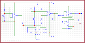
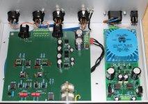
Having seen the excellent measurements of PMA's OPFET preamp, I built a perfboard prototype of Scott Wurcer's device with JFE2140 as the differential pair and 2SK117 in the servo.
In the beginning, I worked with single op-amps, e.g. OPA134 in the servo, OPA1611 in the diff. stage, but the best results came about with an OPA2156 (the input FETs biased at 2mA, as suggested by SW).
The spectrum in the first att. was measured with a differential input signal of 1Vrms (Victor's oscillator followed by a 49724 SE/diff. converter), Hall topology notch filter, Groner's 60dB LNA from Linear Audio vol. 3, and the Cosmos ADC (range 4.5V).
Relative to the output voltage of 2Vrms, the 2nd harmonic is at -143dBc (I'm aware of a possible distortion cancellation here), and the 3rd one at -128dBc.
With 0.1% resistors I measured CMRR of 63db RTI at 1kHz (1V to 2.75V).
However, when used in SE mode, the distortion performance is disappointing.
Referring to the second att. the 2nd is at -85dBc ref. to 2Vrms, and the 3rd at -116dBc (measured directly with the Cosmos ADC, i.e. without notch filter and LNA, positive input at 1Vrms, neg. input grounded).
I've scrutinised my prototype thoroughly and didn't find any mistakes.
Knowing that a standard three-opamp in-amp device doesn't behave in this way, I'm wondering whether this is a peculiarity of the circuit, or I've made a mistake that I'm somehow still myopious to.
Hi, I am sorry for late answering, but I am not visiting the forum often.However, when used in SE mode, the distortion performance is disappointing.
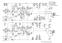
The circuit distortion behaviour with single ended input signal is worse than with the balanced input. It strongly depends on input JFETs matching and IC1 operating point setting, and IC2 input linearity. As an IC2, I use AD797, though the schematics above says OPA134.
The circuit has excellent CMR, very low noise and high 100k input impedance of each input node, I keep using it for such parameters.
I have re-measured it with SE input and balanced output, below you will find the results.


The single ended distortion may relate to the input cap modulation with signal. If ithe distortion is lower with less series resistance between the gate of the FET and the source its probably that. In balanced mode there may be a cancellation of that nonlinearity. I use a cascode input to minimize that effect.
Hello Pavel,
This was a nice surprise - thank you very much for the detailed measurements.
I was experimenting with this circuit as a substitute for an integrated in-amp, like e.g INA849, in a low-gain/low-noise application because up to a gain of some 20dB its output noise is lower than that of the 849.
In post #38 Scott mentioned the need for the CM amplifier to have a large input CM range, hence my using OPA2156 instead of AD797 (which I also tested).
I was doing this work in another (non-english speaking) forum, and a version of the circuit with a cascode was suggested and simulated, but I didn't have the time to implement it properly.
The project has been dormant for some time now, but I plan to return to it.
Regards,
Braca
The single ended distortion may relate to the input cap modulation with signal. If ithe distortion is lower with less series resistance between the gate of the FET and the source its probably that. In balanced mode there may be a cancellation of that nonlinearity. I use a cascode input to minimize that effect.
Yes, there is a considerable difference in working conditions of input JFETs with single-ended and balanced input signal. Vee is the common voltage that feeds source resistors of the input JFET pair.


The single ended distortion may relate to the input cap modulation with signal. If ithe distortion is lower with less series resistance between the gate of the FET and the source its probably that. In balanced mode there may be a cancellation of that nonlinearity. I use a cascode input to minimize that effect.
Simulation has shown that cascoding the input JFET pair does not reduce distortion in single ended input mode.
- Home
- Design & Build
- Equipment & Tools
- Differential take on Groner's LN Measurement Amp