Unfortunately, I do not have schematics for the B1 option. What I do know is that it is an SVO with 2 integrators and a loop inverter, implemented with very precisely matched components and thermally monitored and compensated by the machines's firmware.
The input signal is pre-processed in the analog domain then digitized for the 32-bit DSPs.
Maybe you can share a photo the next time its open. The physical implementation will reveal a lot of secrets and its really important at this level of performance.
Maybe you can share a photo the next time its open. The physical implementation will reveal a lot of secrets and its really important at this level of performance.
This UPL is currently on location, so I can't help. Attached is a picture of its outside, note the typical R&S superbly robust construction and shielding.
I'm surprised that it would not be something like a 30-bit digitally-synthesized oscillator with a tracking filter to further reduce harmonics.
I too, would like to see a photo of where and how this option is installed.
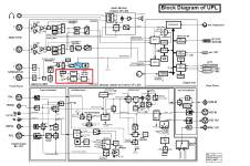
The output of the standard generator is digital while the B1 Low Distortion Generator is analog. Any input would be pre-processed in the analog domain, then to the 20-bit ADC, then into the DSP where it is processed with 32-bit precision. In the attached UPL Block Diagram, the red box encircles the analog B1 Low Distortion Generator, an the blue box encircles the standard digital generator.
Attachments
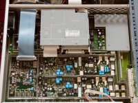
Is this mounted on the underside of the unit? Where exactly is it located?
Yes it is.
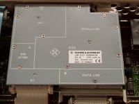
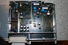
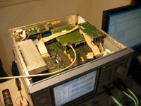
In the attached picture, the front of the UPL is to the right. Note that it is more than a signal connection but it interacts with firmware continually. Its ultra low distortion performance stems from using only high precision components which are thermally monitored through the "Data Link" as marked on the Option.
Attachments
I wonder if that could be user installed or does it require the main board ROM to be flashed with new programming?
I am not sure how easy it is to find one to install - they were expensive to buy new, and installed in used UPL is as rare as hen's teeth. If you find one, hang on to it because another will not likely come around any time soon. The feedback from a dealer in Germany was "Extremely Rare".
R&S refers to their software as "firmware" and it contains the routines to validate option installation status before as well as operating parameters during use. The B1 option is marked as "installed by R&S" in their documentation.
I received the new front panel assembly today it came a week earlier than predicted.
The new panel is not the entire panel. There are no push buttons. It is just the front panel and a thin metal sub-assembly with the ribbon cable. What I discovered in taking my front panel part is that the membrane keypad is a separate assembly that can be taken out. So that's what I did I transferred everything and built up a new panel using the new parts. I also took the opportunity to clean up any fuss that was inside the LCD panel from when I had done the repair of the ccfl lamp assemblies.
So now the unit is repaired the keypad Works everything works and I put it in service. Oddly enough, they have not charged my credit card yet. We'll see what happens. $575 did seem like a lot for two little pieces of metal with a piece of ribbon cable and not the entire front panel assembly which is what I thought I would receive. Oh well, mistakes made and Lessons Learned.
Audio analyzer RS UPL - service manual
I need copy of complete service manual (volume 1 and 2) without schematics for RS UPL audio analyzer in pdf format... I can arrange to copy of schematics for RS UPL, original last firmware v3.06 from RS... Please send me some message if you have service manual in pdf... thanks.
I need copy of complete service manual (volume 1 and 2) without schematics for RS UPL audio analyzer in pdf format... I can arrange to copy of schematics for RS UPL, original last firmware v3.06 from RS... Please send me some message if you have service manual in pdf... thanks.
UPL B1 option
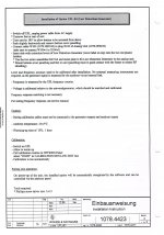
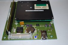
Here you have some information about B1 option unstallation. Does not require any special operations. Do the hardware installation and then run user calibration routines.
73 Juha oh2nlt
Here you have some information about B1 option unstallation. Does not require any special operations. Do the hardware installation and then run user calibration routines.
73 Juha oh2nlt
Attachments
UPL CPU board
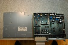
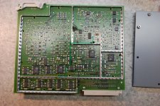
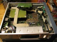
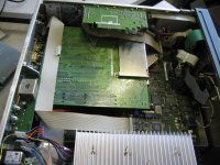
There are at least two different types of cpu boards for the UPL. IMG_2610 is the older PC motherboard style CPU board. IMG_1205 is the newer industrial PC on the carrier board implementation. I have this one in my UPL. There are also Ethernet interface on this board. I have not found any R&S support for the Ethernet. It would be nice way to transfer measurement results from the UPL box. Industrial PC is propably some Kontron brand OEM board. I have tried also identify it and get OEM network drivers for the board. However no success yet.
There are at least two different types of cpu boards for the UPL. IMG_2610 is the older PC motherboard style CPU board. IMG_1205 is the newer industrial PC on the carrier board implementation. I have this one in my UPL. There are also Ethernet interface on this board. I have not found any R&S support for the Ethernet. It would be nice way to transfer measurement results from the UPL box. Industrial PC is propably some Kontron brand OEM board. I have tried also identify it and get OEM network drivers for the board. However no success yet.
Attachments
I need copy of complete service manual (volume 1 and 2) without schematics for RS UPL audio analyzer in pdf format... I can arrange to copy of schematics for RS UPL, original last firmware v3.06 from RS... Please send me some message if you have service manual in pdf... thanks.
Jiri,
You have PM (I can help with your UPL, we have a few UPD's the UPL's bigger brother - they share much the same with the UPL (such as the low distortion option).
My UPD's are getting old now (like me) but with a bit of TLC they can be kept going.... your UPL will be much the same.
Incidently, I had the opportunity to play with the new UPV, yet the UPD still has lower noise floor - and seems much easier to use on the lab bench.
R&S UPL Ethernet connection
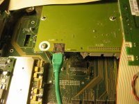
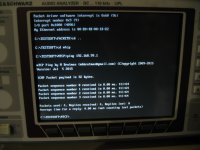
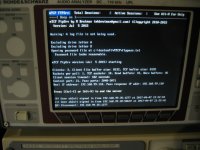
I got my motivation back and started really to solve the UPL hidden Ethernet problem. Ethernet chip on board is Davicom DM9102. After some search I found dos packet driver set for it. This generic driver however did not work in the UPL board no matter what I tried. After more recearch I found that DM9102 resembles very much DEC 21x4x Ethernet chip family which was widely used in the old PC network cards. After some try and fail tests I found CNet Pro 200WL network card packet driver working perfectly with the on board DM9102 chip.
Next step was to choose data transfer software/tools. I found one very good package containing everything neded and specifically designed for old DOS computers.
TCP/IP applications for your PC compatible retro-computers.
mTCP TCP/IP applications for DOS PCs
There is also full featured FTP server in this suite.
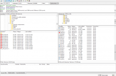
Last piece was just some dos batc files to load and unload network and FTP server. Now transfering measurement pictures out from the UPL is easier than ever. Also UPL disk/file maintenance is easier.
I got my motivation back and started really to solve the UPL hidden Ethernet problem. Ethernet chip on board is Davicom DM9102. After some search I found dos packet driver set for it. This generic driver however did not work in the UPL board no matter what I tried. After more recearch I found that DM9102 resembles very much DEC 21x4x Ethernet chip family which was widely used in the old PC network cards. After some try and fail tests I found CNet Pro 200WL network card packet driver working perfectly with the on board DM9102 chip.
Next step was to choose data transfer software/tools. I found one very good package containing everything neded and specifically designed for old DOS computers.
TCP/IP applications for your PC compatible retro-computers.
mTCP TCP/IP applications for DOS PCs
There is also full featured FTP server in this suite.
Last piece was just some dos batc files to load and unload network and FTP server. Now transfering measurement pictures out from the UPL is easier than ever. Also UPL disk/file maintenance is easier.
Attachments
Unfortunately not with this software combination/methode. DOS is single user environment. When FTP server runs nothing else happens in house. Thinking other possibilities main limitation would be DOS memory space. R&S already runs their UPL package with EMM sys which means that there are already need for more than 640k memory.
- Status
- This old topic is closed. If you want to reopen this topic, contact a moderator using the "Report Post" button.
- Home
- Design & Build
- Equipment & Tools
- LCD Backlight for Rohde & Schwarz UPL?