That pretty much negates the advantages for me. I don't have to shut down the UPL to copy files off the floppy disc. If the UPL has to be shut down to do file transfers, the time lost pretty much negates the savings from faster transfer speeds. Most of the EPS files I write to floppy are 13-18K and only take a few seconds to write.
UPL external Ethernet connector
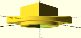
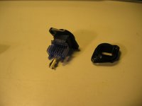
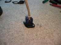
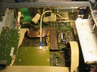
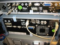
Final step was to implement external connector for the Ethernet. I do not have digital audio option in my box. There are several connector holes reserved for this option covered just with plastic sheet. My brother kindly 3D printed adapter for the RJ45 jack. Better place would have been in the back side but available spare holes are at front side. Have to live with this. Pictures tells rest of the story.
Final step was to implement external connector for the Ethernet. I do not have digital audio option in my box. There are several connector holes reserved for this option covered just with plastic sheet. My brother kindly 3D printed adapter for the RJ45 jack. Better place would have been in the back side but available spare holes are at front side. Have to live with this. Pictures tells rest of the story.
Attachments
1) Neutrik has RJ45's in that pattern if you need them.
2) There were some ancient DOS multi-tasking proram environments and maybe you can run the network suite as a "terminate and stay resident" "TSR" program. if its really from the dos world it may be possible. Also which version of DOS is it running? Will it run DOS 4.0 multitask or even 8.0? https://en.wikipedia.org/wiki/MS-DOS#Versions .
Really ambitious would be running the analyzer in a dos window on Win 10?
UPL external Ethernet connector
Thank you for the comments.
Of cource I have used them if it have been possible but unfortunately in my UPL all rear panel XLR holes are in use. Ref In/Out may look free but another installed option block them.
Yes I understan what you mean. LAN workstation agents behave jus as you explained. However I wanted to disturb UPL application as little as possible and choose different approach. When UPL is running I do not have any "foreing" software components loaded or running. Packet driver and FTP server can be easily loaded when neded and more important feature is that they also can be unloaded before UPL restart. LAN workstation SW and drivers are more difficult stop and clean from the memory.
This is one way to do the measurement results transfer and UPL HDD maintenance. I am interested to hear experiences about other implementations.
I have not ever seen but some UPL66 sales brochures talks about Novell LAN option. Nothing found about this from R&S www pages. Also google search gives nothing about this subject.
Attachments
I was testing a Hafler XL600 amplifier today and operating it in bridge mono mode. Normally, this is not a problem, as I have the analyzer inputs floating and the dummy load is not connected to ground reference anywhere.
I was testing to find out a safe value for speaker fuses at the output of the amplifier. When the right channel fuse opened up, the amplifier output relays started cycling. So I replaced the fuse, and powered it back on, but the amplifier was oscillating at an RF frequency and putting out 60V RMS at some frequency over 200KHz. If I disconnected the UPL generator from the amplifier, the oscillation would cease. In the course of trying to track down the cause of instability, I discovered that the UPL generator output could not be turned on anymore. In THD measuring mode, the Output Off indicator only blinks when I press the output on/off button. In other modes, I can hear a relay kick in and out rapidly (50mS or so) as the light blinks.
I shut off the UPL and waited a few minutes, then turned it back on. With nothing connected to the UPL, the generator output will not turn on still. This is perplexing, as the generator side was connected only to the input of the amplifier.
I'm wondering if some safety device like a fuse inside the UPL may have opened up?
UPDATE:
I tried feeding signal from another generator into the amplifier. A voltmeter confirms that there is output from the amplifier of the expected magnitude. However, the UPL does not register any input.
Generator output won't turn on and analyzer seems to be also non functional.
Last edited:
Mark,
Oh dear - I've seen similar with UPD - I have 6 units and over 25 years have seen 2 damaged in the same “odd” way (testing power amplfieres).
The "Fuse" is the BD140 / BD139 output devices and associated resistors etc. You will also find that the LM317 in the PSU has also gone short circuit (atleast on the UPD).
If your unlucky, you will also find the attenuator components damaged, worst still the PCB burnt!
https://www.dropbox.com/s/zumyac2t3uokok8/resistors.jpg?dl=0
Good luck, my heart goes out to you on this one – the first time it happened to me I felt sick…
If it’s only the output devices / PSU then its all repairable – if it’s the attenuator components damaged / PCB then you can still repair – but knowing the PCB is damaged is a disheartening… If you need to change the attenuator components then match them to 0.1 %
On my UPD's I've never had problems with the analyser section, but it might be due to the PSU damaged when the Generator went pop...
Obviously my remarks concern the UPD - but I "suspect" that the UPL shares common circuits....
Last edited:
In the case of this UPL, the boards are not damaged, but several SMD chip resistors have burnt. It almost seems like the unit was damaged by lightning.
The resistors connect between ground and some part of the output attenuator of the generator. Shown here:
https://www.dropbox.com/s/x8l7e21k36rqs6z/20170413_213225.jpg?dl=0
The other problem is that nothing else works, except the UI and that's run by the host computer. The audio electronics seems dead. Ie., spectrum analyzer mode displays the X-Y grid, but no trace, no noise floor that would normally show up. Does not indicate the presence of input signals.
I checked all of the round fuses in the PSU and they are good. I could find no damage on any of the circuit cards, except for the area photographed above, which is under a grey metal cover plate.
The RF wasn't all that visible on the output of the UPL (I normally use the headphone out to feed ch 3 & 4 of my 4 channel scope) because it was probably outside the bandwidth of the UPL, but a DVM with a 2MHz bandwidth showed 60V RMS when the amp was on, between cycling the speaker protection relay. In my experience (having blown up a HP scope 30 years ago while measuring a VHF RF amplifier---damage being deep into the heart of the scope, not just input attenuators), high frequency RF events have a tendency to behave like a lightning strike, damaging things that are layers behind the outside interface. This unit is totally dead, excepting the host computer and display. The only thing that responds is the keypad. I can call up programs and enter data, but there's no output and there is no display when external signal is input. The fact that modes like spectrum analyzer do not even produce a trace, indicates the possibility that the DSP chips may have been destroyed. My intuition suggests this goes a lot farther than a few attenuator resistors and op amps.
I have a hunch that when the right channel speaker protection fuse opened up, that was also connected to the low side of the UPL (amplifier was bridged) and the other output of the amplifier remained connected as its fuse did not open. That incident may have caused a sudden DC shift and current may have flowed from the input ground. The XL600 does have a 5 ohm thermistor between input shields and ground. When I replaced the fuse and powered it back up, I got 60 V of RF on the outputs, but didn't realize it immediately. The hint was the output relays cycling on/off/on. So either the fuse opening/sudden DC common mode current flow, or the RF when it came back on, did the damage.
I'm going to contact R & S and explain what happened. After having soaked me for $750 for a new front panel a couple months ago, I doubt they are going to help me out on the repair, but I must at least make the effort. Otherwise it's a $4K calibration/repair fee, at the minimum.
The other option is to shop around for a decent used Audio Precision test set, which I've rarely seen under 10 grand. I don't know if they're any better protected. Meanwhile, I put the old, trusty Tektronix AA501 and SG5010 back in service. I've had "RF" events like this happen with those units and the SG5010 will simply lock up the controls and all I need do is power cycle it to clear the fault. It's evidently much more robust than a $40K analyzer from years in the future.
Mark,
I'd swap a fully working AP System 1 Dual Domain with full DSP etc. and USB interface lead for your R&S UPL in its current condition....
I also have a full Audio Precision SYS2722 + PSIA2722 + AUX0025 + SWR2122U + APIB/USB adapter for sale, say US$15K... Pass AP's System two "deep" testing (takes about 20 minutes to perform the full test run).
The SYS2722 is AP's highest Spec. dual domain unit, with all units 8 / 10 condition with nothing mote then normal scratches from wear and tear (no dents) with all connectors undamaged – SYS2722, AUX0025, SWR2122U & APIB/USB tested and working, the PSIA2722 is untested as I’ve displaced the interconnect leads - US$300 from AP!
I'm pretty sure as I can be from afar, that the Generator output stage has also blown taking down the PSU rails and hence why nothing else works...
Last edited:
That's a nice offer, however there are some concerns:
Generator flatness +/- .25dB
Generator output impedance min 50 ohm
Needs external PC?
No RIAA compensation filter?
That information came from this document:
https://www.google.com/url?sa=t&rct...88-LE51Pr-zXW__eA&sig2=tDOPZdZXtXxPItGvp0zTPw
I really like how the UPL works, and its adaptability to various tests and custom test setups that I've built for it. That A-P unit is also pretty old (1989) and there may be other interoperability issues with finding a compatible PC and O/S to drive it and run its applications.
I have an e-mail discussion going with Greg at R/S. He thinks the analog board is probably bad. Will have to see where this discussion leads.
I missed a great deal on a UPL with the digital i/o option in Denmark last month for $799 sale price. It looked in mint condition, too. Had I known that existed, I would have bought it just to have a backup at that price.
Mark,
For sure the UPL is a nicer machine to use - in fact I hate the AP's and dont understand how they have become the industry "standard".
I use the AP1's with Windows laptops running XP with Udo's USB cable - I'd say that software is more available for older APs then the R&S...
Unbalanced Zout is 25 ohms
RIAA EQ curve is standard for the Generator - you just need to enable the option.
The AP system 1 Dual domain has the Digital I/O option (to 48KHz) etc.
I'm pretty sure the generator is flatter then +/-25dB atleast across most of the band - I can run the AP1 test when I have time.
The FFT feature is slow - its not realtime, first it captures the Data then sends to the PC.... pretty useless. Its my opinion that the APs are great "Analogue units" - well in fact everything is based around the analogue notch / tracking filter, with the Digital features added as an after development...
If I had time on my hands, I'd design retrofit ADC / DAC / DSP to the units and that would be impressive.
The later AP's are better, but the software is horrific to use on the Lab bench - I'm selling my very little used SYS2722 as I'm investing in a small SMD line.
My offer stands if the UPL is effectively scrapped due to repair costs... I'm confident I can repair the UPL, there's northing on them thats hard to fault find with a bit of time (no Custom RF modules you might find in HP units etc).
Dont be scare of by its apparent complexity, the UPL is nothing more then a collection of standard audio circuits. It always surprises me how seasoned skilled engineers are scared off by the thought of repairing test equipment - as if there was anything different about them... if you have the skill to repair Amps / Line stages / ADC's / DAC's & PSU's then you can repair your UPL!
Last edited:
I do appreciate that offer, in the event that I am forced to give up.
I am currently troubleshooting the generator section (the analyzer is broken too).
I've gotten as far as K238 with signal from the gen. K238 is part of the gen ovrld circuit and is not energizing, so signal is stopped short of the HP DIFF amplifier.
What's making it hard for me is the small size of the components.. mostly SMD. My probes are too big and my eyes lack the acuity to see things this small, even with my reading glasses on. Most of the equipment in my shop was rescued and repaired by me, so repairing test equipment is no stranger to me. But I'm used to older, discreet circuits with full sized DIP ICs. I used to repair Orban Optimod 8100A and other broadcast audio multiplexing/processing gear, so the density and complexity is nothing new.
If the overload interrupt is malfunctioning, I wonder if that would disable the analyzer too? I am hoping the two problems are related.
Mark,
My experience is that the Output stage is fired - if its like the UPD then there will be BD140 / BD139 transistors on heatsinks as output devices, the output protection is indicating trip.
Short Circuit output devices will also pulling down the PSU and hopefully why the analyser section is non functional.
If the output devices are popped - then also check the driver stage. The good thing is you have 2 audio Generator output channels so you can compare between each other.
My UPL has these four transistors, too. I've checked them and the readings are between 2.5K to 11K and varying, as capacitors charge up from my probe voltage.
Somewhat confusing is what to use for ground reference when measuring voltages--the UPL has several different grounds and they are not at the same potential! I didn't find 22V that is indicated on the diagram on any of those devices, but I may not be referencing against a valid ground.
I had a peek down at the power supply heatsink.. had to do a double-take--there must be 15-18 regulator ICs on that sink! Looking for good test points, but found none.
I need to look deeper into the power supply, as I suspect my amplifier under test chassis may have taken on a potential momentarily when it went into oscillation. I found out tonight that the high bandwidth (over 100V/uS) output stage is unstable with the input jacks tied to chassis as they come from the factory. I isolated the jack grounds from chassis and the amp is stable.
When Hafler amplifiers go bonkers, they can make their chassis assume elevated voltages. I had a DH500 suddenly go berserk in the rack in my studio and pulling the amp out of the rack while powered on, saw sparks when the chassis contacted the rack rails. I think the UPL output ground got hit and that common mode impulse, not unlike the sort of thing that happens with nearby lightning strikes, may have damaged components in the power supply. So I need to find out where to test for each of the numerous regulators' outputs and what their voltages should be.
If I succeed in repairing this UPL, I am going to have to come up with a means of providing fusable links between my loads, inputs and the UPL. Perhaps 10 ohm 1/10W resistors in series with every connection to the UPL.
Protecting inputs and outputs of test equipment is difficult, especially when the performance requirements are high. I recently lost the ouput section of a Krohn-Hite 2200 driving a clock motor. I never would have guessed that even with a 50 Ohm resistor the mnotor could kick back enough energy. The special output transistors are expensive and hard to get so I'll be much more careful.
What could make sense is an interface box for both in and out with fusing and clamp diodes in the right places. Put the fuse holders on the front panel (speaking from experience). 250 mA fuses won't add distortion on line level stuff. Its also a place to patch speaker loads etc. and establish a central common ground point.
A watt meter on the power can also be useful to see if something is misbehaving. And a GFCI for safety.
If you unearth any schematics that can be shared I'm interested.
Yeah, my thinking is to have 10 ohm resistors of very low wattage that will open up in the event of a sudden, unexpected amount of common mode current.
Clamp diodes can be tricky. They introduce non linearity and that's not good when you're trying to measure .0003% THD. Maybe on the generator output, but for the analyzer side, something else is needed because the expected input can be up to 110V RMS.
I do have schematics. PM me and I'll give you a link to my Dropbox folder.
So far, there's no 20V rails on the BD139/140 devices. I see about 1.5 V and 13.5V, far from what I expect to see. Even less on the other side of R664 and 669.
Trying to get the power supply out, but the mounting screws to the PCB are hidden under the side trim opposite the handle side of the unit. Not sure how to remove that trim to reveal the screws.
UPL input protection
At the input side there are already diode clamp protection. First opamp inputs are clamped to about +/-10V. Attenuators are before the diodes. Quite clever circuit is to use small incandescent lamps (60V 0.02A) as protection devices in the lowest attenuation step (direct). In normal operation filament is cold and low resistance. When clamping voltage is reached filament warms up and lamp R rises very quickly.
At higher attenuator steps attenuator input R is already so high that no other devices are not neded.
That's identical to some Tektronix gear I have, using the same sort of lamps.
I've established that something is loading down the 20V rails. Disconnecting the ribbon cable supplying power to the analog board, the voltages are correct with no load. I'm starting to suspect N83, a 5534 op-amp with a ceramic package, since the four power transistors are not shorted.
I've established that something is loading down the 20V rails. Disconnecting the ribbon cable supplying power to the analog board, the voltages are correct with no load. I'm starting to suspect N83, a 5534 op-amp with a ceramic package, since the four power transistors are not shorted.
- Status
- This old topic is closed. If you want to reopen this topic, contact a moderator using the "Report Post" button.
- Home
- Design & Build
- Equipment & Tools
- LCD Backlight for Rohde & Schwarz UPL?