


Yes,
Not a problem as long as I have the camera working and kid
or mom doesn't run off with it or the interface cable. ; )
Do you want a pic of the A5 board looking down?
or the whole back of the A5 board pulled.
Solid or Transparant?
I can back light it so if you want to see through
the board a little bit you can.
I'm going to go to my parts store and buy some stock and
cut it to fit, to make a new back board.
I don't think they have aluminum in stock.
They do have sheet's of copper, actually
foamed core copper sheeting. That might
even be better for shielding. Did you just
run a wire from A6 ground to A5 ground or A7?
or elsewhere in the unit.?
Flip the unit over and remove the bottom cover. Take a shot of the bottom of the back plane.

David,
Yeah I saw that too. And have diodes paired up off board, etc.
And the special op-amps they put in some places complete
with hand written stickies on them.
But then it comes down to just what we do here on DIY...
just make stuff work better. Why pay for a new production
run when we can just mod something or jumper, or parallel
it or put a part in series.
Richard kind of said it somewhere in the long distortion thread,
ok to cut any trace, do any thing needed to get it working right
or working better.
Demian told me when we were working on the HP339A
in person, with jumpers and connections going
every which way with all the measurements going on...
"it feels like we're doing physics!"
As they say,
it IS what it IS. ; )
 PS - What are you going to do, embarrass Shibasoku or something?
Yeah I saw that too. And have diodes paired up off board, etc.
And the special op-amps they put in some places complete
with hand written stickies on them.
But then it comes down to just what we do here on DIY...
just make stuff work better. Why pay for a new production
run when we can just mod something or jumper, or parallel
it or put a part in series.
Richard kind of said it somewhere in the long distortion thread,
ok to cut any trace, do any thing needed to get it working right
or working better.
Demian told me when we were working on the HP339A
in person, with jumpers and connections going
every which way with all the measurements going on...
"it feels like we're doing physics!"
As they say,
it IS what it IS. ; )
PS - What are you going to do, embarrass Shibasoku or something?
Last edited:
Power went out yeah.
Right when I was starting to test the amp. (
(
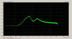
In the mean time, My link didn't make it yet.
So here it is.
Original (64000/30avg):

w/back plate (64000/50avg):

.Any other size difference complements of Microsoft and I can't undo it.
David, yes, I'll get it for kyou.
Right when I was starting to test the amp.
(In the mean time, My link didn't make it yet.
So here it is.
Original (64000/30avg):
w/back plate (64000/50avg):
.Any other size difference complements of Microsoft and I can't undo it.
David, yes, I'll get it for kyou.
Last edited:
Yep, will post componant side later this afternooon.Sync can you put a pic of the A3 board top?
I have my stack in place right now for testing my McIntosh MC250 amp.
When finished, will take pics of the boards.
Now I wished I just took pics of the whole thing when I had it apart.
My excuse is I can't delete pics from mem cards any longer--thanks
microsoft. Plus all the batteries were dead and chargers were
somewhere where I didn't find them for a while.
I've got one working currently.....on charger, but no interface to
computer.
I've got two with interface cable but slow with full mem card.
Oh the joy.
Here is the pic of the A3 board. I emailed you a larger
one if you need to zoom in on specific parts.
Hope this helps.

As to ideas for the 3H?
I'll cop out and ask if you checked the usual suspects.
Let me think about that while I try to swap boards
and see if the old McIntosh I'm working on is still working.
More stuff to do...while baby destroys the house.
one if you need to zoom in on specific parts.
Hope this helps.
As to ideas for the 3H?
I'll cop out and ask if you checked the usual suspects.
Let me think about that while I try to swap boards
and see if the old McIntosh I'm working on is still working.
More stuff to do...while baby destroys the house.
Sync-
1) Make sure the 3H is not from your source.
2) the DC offset on the input has influence on 3H
3) a linear plot makes it easier to see the harmonics
4) the 60 Hz and 120 Hz will limit things. Getting those down (use a battery powered source) will help.
5) Max in is 100V. Don't overload it with the MC350.
That is good Demian thanks for the heads up.
Thanks. I'm just working on a lot of pics of the McIntosh
now. I did basic square wave testing at 50HZ, 100Hz,
1kHz, 10kHz, 50kHz, & 100kHz.
Max voltage output was about 43Vp-p on the scope
with 1V rms input, or 0dB. Which equals 2.83V p-p
on the scope.
I'm not using the "proper load" I went down to 5.1 ohm
75W dale resistors to roughly emulate a real word speaker.
I have to go back through the input driver board and measure/
look at the signals on the board before they go to the Output
Driver PCBs. Yes, a real antique amplifier coming back to life.
Here is a link to the thread - LINK.
Glad you stopped by to say hi, hope you are doing well
and enjoying your new digs. : )
It will take a bit to crop and list the new pics.
Oh wow,
I just realized I need to pull the batteries from my old HP3551A Transmission
Test Set. I've never used them and assumed they were bad. They are still
in it. That is a complete and shielded unit...with Oscillator and Counter
and does 135, 600, 900 ohm loads. It also sends and receives too.
I'm thinking the battery pack would cost more than the unit itself cost me.
Now, If I could just find a lid for it. It gets all scratched up moving it about.
- Home
- Design & Build
- Equipment & Tools
- ShibaSoku Automatic Distortion Analyzer