Nice! I really wonder why scopes don't come with some sort of galvanic isolation built in. I imagine the ability to measure waveforms across a component without worrying about "ground"' would be tremendously useful. My multimeter never disappoints but my scopes often ask me "Why did you try that? " ")
Last edited:
This is really nice, and it is good to see it is effective. I have two questions, hope I didn't miss their answers earlier in the thread.
The two optional ground switches provide nice flexibility. What is your general experience on which switch positions work best?
My first version did connect grounds, just cutting the ground connection lowered noise by about 50%
As 'not connecting ground' ensures 100% galvanic separation I would advice any one, when connecting measure equipment, to leave the ground disconnected.Just for added safety, have you thought about the possibility of connecting back-back paralleled diodes from the input safety ground to the output safety ground, maybe switchable? I realize they would add some stray capacitance depending on their size, but this might be smaller than the strays going through the transformers anyway.
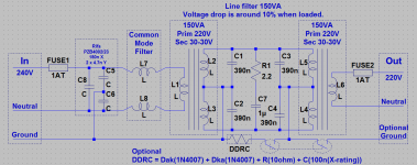
That is what I always do, I use a circuit that I call a DDRC (see also http://www.diyaudio.com/forums/analogue-source/218625-paradise-builders-90.html#post3314964) I have added an updated circuit that includes a DDRC. Experiments should be done to determine if the R and or the C (in the DDRC) are needed/wanted. As using a disconnected ground functioned better I never gave the ground connection a second thought
Also for safety, I wonder if the mains GFI or a GFI on the output side could play a role in increased safety in the event of some fault (definitely not sure about the latter). There might be a way to sense a fault and "deliberately" trip the mains GFI in a relatively non-intrusive way, since it takes little current through the safety ground to do so.
I do not think that safety is an issue, except for the fact that one needs to build a good sturdy box, with ventilation, that encloses it all (this is mains connected and thus dangerous!). When the galvanic separation is complete touching any of the output wires poses no hazard (but is not advised), only touching both, at ones, poses a danger. As the equipment is using CE (or what ever is you local) wiring, and you are using a good box, and using good wires and connectors, there should be no safety issues. This isolation system is intended to be used with measuring equipment that will contain it's own fuses and circuit breakers. OTH
using a input GFI may be a good idea.Attachments
Last edited:
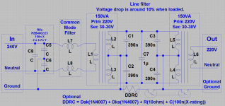
Jan, to answer your remark about voltage drop, the measured voltage drop under load is about 10% this is within specification of all the measuring equipment that I have connected. An input voltage of 240Vac gives an (loaded 150VA scope spec) output voltage of 220Vac (you must make sure that the connected equipment works fine at about 200Vac). When building a filter like this one needs to check the voltage ratings for the equipment that will be connected.
Thanks Frans, very useful info.
A question: did you try (or consider) a small resistor in series with the capacitors in the middle, to make them lossy?
jan
Thanks Frans, very useful info.
A question: did you try (or consider) a small resistor in series with the capacitors in the middle, to make them lossy?
jan
No I did not
I do not have the equipment to verify the usefulness of such a change, as I think the such a change would be small. Maybe someone else with the correct equipment to test this could do/verify that.These ideas are used in the Monster HTPS7000 that Richard Marsh designed. For that product we are required (UL-NEC) to use GFI's at the output of the isolation transformer which makes sense. GFI's are more effective safety solutions that a simple ground. The function of the ground on the AC distribution is not well understood. Its about making sure the fuses/circuit breakers open under fault conditions. "Ground" not really all that useful for reducing noise. We provided a switch to leave the isolation transformer floating or ground the center tap for the load (balanced power) because different situations will have less noise with different settings. The power is always isolated from the incoming ground.
Jan- at the levels and impedances here meaningful resistor values tend to be close to the cap ESR's. However paralleling several caps of different values can help. Adding ferrite beads on the transformer leads can help (they are resistive losses at high frequencies) Ferrites can work better than a series resistor on the caps. The caps will interact with the transformer and wiring in unpredictable ways. Figuring it out requires a network analyzer since its hard to see the changes any other way.
Jan- at the levels and impedances here meaningful resistor values tend to be close to the cap ESR's. However paralleling several caps of different values can help. Adding ferrite beads on the transformer leads can help (they are resistive losses at high frequencies) Ferrites can work better than a series resistor on the caps. The caps will interact with the transformer and wiring in unpredictable ways. Figuring it out requires a network analyzer since its hard to see the changes any other way.
No I did not
You could see if there is a difference the same way you did before.
It may make a usefull difference - then again it might not.
Might be worth a try comparing to your current results.
jan
You could see if there is a difference the same way you did before.
It may make a usefull difference - then again it might not.
Might be worth a try comparing to your current results.
jan
I will try it, 10ohm and maybe 2ohm in series with 1u?
Its about making sure the fuses/circuit breakers open under fault conditions. "Ground" not really all that useful for reducing noise.
That is a good point
could you suggest a type, maybe from the Mouser stock, for this 150VA application.Since i designed the HTPS-7000 iso-filter model- for audio and video it starts filtering at a much lower (audio) freq and has over 100dB of rejection and isolation. The isolation transformers are triple shielded special design (similar to TOPAZ) I had custom made. Nothing.... not even lightning transients gets thru. I would suggest using larger filter values for test apps and for audio applications. This 'suggestion' is based on a LOT of testing.
BTW--If you can find a Monster -7000 for sale, buy it... nothing else exists that is as thorough for the price. CE/UL tested and approved as well.
THx-RNMarsh
BTW--If you can find a Monster -7000 for sale, buy it... nothing else exists that is as thorough for the price. CE/UL tested and approved as well.
THx-RNMarsh
Last edited:
Since i designed the HTPS-7000 iso-filter model- for audio and video it starts filtering at a much lower (audio) freq and has over 100dB of rejection and isolation. The isolation transformers are triple shielded special design (similar to TOPAZ) I had custom made. Nothing.... not even lightning transients gets thru. I would suggest using larger filter values for test apps and for audio applications. This 'suggestion' is based on a LOT of testing.
BTW--If you can find a Monster -7000 for sale, buy it... nothing else exists that is as thorough for the price. CE/UL tested and approved as well.
THx-RNMarsh
This is the one? Monster Power Pro 7000 PRO7000 Power Conditioner | eBay
You Must place a fuse in strategic locations.... caps fail/short and so do transformers windings. Overheating will cause serious damage to property and life if not fused properly.
Use only CE/UL approved parts for ac line use. If it isnt marked as such dont use them.
Thx-RNmarsh
Use only CE/UL approved parts for ac line use. If it isnt marked as such dont use them.
Thx-RNmarsh
yes.
I will try it, 10ohm and maybe 2ohm in series with 1u?
Probably just 1 ohms to try it.
You Must place a fuse in strategic locations.... caps fail/short and so do transformers windings. Overheating will cause serious damage to property and life if not fused properly. Use only CE/UL approved parts for ac line use. If it isnt marked as such dont use them.
Sure, as I said, use good (quality) parts only!
Probably just 1 ohms to try it.
O.K. I will try 1 and 2ohm
and I use the DSO with large amount of averaged measurements to see the effect also I will add fuses and update the published circuit, but first the BBQ needs attention As the equipment is using CE (or what ever is you local) wiring, and you are using a good box, and using good wires and connectors, there should be no safety issues. This isolation system is intended to be used with measuring equipment that will contain it's own fuses and circuit breakers..
But fuses must be used, and a GFI is recommended (I am trying to locate a fitting one, if you know one then let me know).
Last edited:
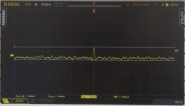
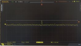
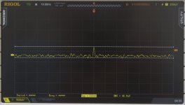
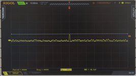
These are the results of adding (or not) a small resistor in series with 1u filter capacitor.
1: Left: No Filter
2: 0 ohm
3: 1 ohm
4: Right: 2 ohm
It looks like 2 ohm is the winner (but I have to say that the noise captured is pretty random). It is not the peak (about 500 uV pulse) that suggests this to me, but the other random noise seems lowest in the last picture. Both 1 and 2 ohm are measured to be 46uVrms.
Attachments
Last edited:
And here is the FINAL circuit! Test must be done with larger values of C7 (10u or even larger?). As I do not have a useable capacitor at this moment, this has to wait. R1 is added and is currently 2.2 ohm, the difference measured is small (and may be non existent, but the pictures in the previous post seem to suggest that the 2.2 ohm is the best value). Someone with the capability to do exact measurements is invited to test this
Attachments
Last edited:
I do have the equipment but without your specific transformers and cap it won't be meaningful. There are several areas to look at-
1) line harmonic reductions.
2) HF noise, significant to 30 MHz or so
3) Common mode noise
The harmonics are a complex issue and a surprising amount of the power needed for a rectified load comes in 5th and 7th harmonics.
HF noise requires a network that allows connection to live power or a closed system to measure attenuation and gauge from that the probable reduction in noise.
Common mode noise is easiest to measure a common mode currents if you have a suitable current probe.
Ofcoure you have two subsequest measirement issues. First the noise floor of the measuring system and whether it has adequate rejection of ground leakage noise current when connected to the thing you want to test. Ultimately you are testing for the DUT's noise rejection, which you can't see until all the other contaminants are removed.
I did not say specifically earlier that the GFCI goes at the output or it won't do anything useful. I don't know if there is much difference among them. It is a very mature business. The devices measure the common mode current and when it exceeds a threshold (10 mA?) on L+N it trips, opening both L and N. EU applications and devices will be significantly different because voltages frequencies and grounding practices are different from the US and in different EU countries (and others around the world).
Here are the specs: http://www.ul.com/global/documents/...wsletters/electricalconnections/january09.pdf Basically a US GFCI will trip around 6 mA or more.. The UL filter spec limits leakage to something like 10 mA so this is where the specs collide. A microamp sensitive GFCI could easily trip from the leakage of a power transformer to its housing.
- Home
- Design & Build
- Equipment & Tools
- QuantAsylum QA400 and QA401