I'll have an error amplifier with that
Getting a little more complete:
Getting a little more complete:
An externally hosted image should be here but it was not working when we last tested it.
Getting a little more complete:
An externally hosted image should be here but it was not working when we last tested it.
Nice, thanks. Wouldn't it better to swap the location of the pot. I.e. fixing the divider from the output and the potentiometer varies voltage from 5V reference instead?
Ale
Nice, thanks. Wouldn't it better to swap the location of the pot. I.e. fixing the divider from the output and the potentiometer varies voltage from 5V reference instead?
Ale
The circuit I showed is essentially that appearing in "The Art of Electronics" without the compensation and current limiting. It's just an inverting amplifier.
For the microprocessor controlled HV supply reference was a 10-bit DAC with a 4.096 Volt reference and some level shifting to get the MOSFETs to respond linearly to the DAC. I stated my preference to NOT use a potentiometer in the HV voltage divider. Select a value which works and solder it in.
I only ran mine in a range of 0 - 400V, so ymmv.


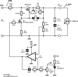
Have reworked circuit to include the voltage feedback regulator as per latest suggestions.
Voltage regulation is now done on the +5V reference side. I have a nice 10T 100K pot that will help in smooth setting of the output voltage.
Q1 is now BUJ302A (1000V NPN) to ensure the pass section is bulletproof. Probably don't needed, but got it at hand and want to ensure that the IRFPG40 and BUJ302A survive any accidental output short.
I have added R12 and C3 to improve the HF response of the circuit.
This one simulates quite well, so will give it a go unless anyone spots anything to improve. I will need to etch a small PCB to fit this out.
Thanks for helping out so far!
Ale
Attachments
Hi Ale,
Yes, I can vouch for the Horowitz & Hill Circuit, too. Vouch for its operation, that is, but if you connect it to a 300BSE amplifier - it absolutely destroys the sound! As in - it removes every nuance from the music.
But for testing things it will be fine.
Some ideas:
M1 needs a gate stopper too. On high voltage supplies I prefer the value of stoppers to be 75 ohm to 220 ohm). connect nothing at all to the gate side of the stopper (it's there to isolate the antenna-effect of the gate wiring - adding zener leads etc at this point will defeat the stopper action, to some degree).
M1 gate can be protected with only one zener, cathode to gate.
Is M1 in a TO-247 package? for a variable supply, M1 might have 500V across it, and so you need all the power handling you can get. Also, TO-247 isolates HV better.
100pF Wima FKP2 across R7 may be helpful to prevent phase lag at the opamp feedback-input. We'll need a 12V zener across R8 to protect the opamp, especially if that cap is fitted.
- R9 will probably need to be lower than R10, to make sure the gain is below 1 at the frequency where phase-margin vanishes. Maybe 2,2K.
Even with the opamp gain controlled at high frequency, the gain of M2's stage is too high to be sure at HF. If you have a high-voltage RC series network across R2, you can tailor the response after building the circuit (test with pulsed loads, adjust the Zeros' RC values to get the neatest response.)
- normal resistors have limited voltage durability - even 2W types are only good for 500V. Making R7 out of 2x 2W series-connected parts
(if you need small size, the Welwyn LHVC resistors give 1600V durability for small size and price:
LHVC2010-1MFT4 - WELWYN - RESISTOR, 1M 1% 2010 | Farnell United Kingdom
using the same selection for R2, if the supply has a wide adjustment range.
I would be tempted to put a ferrite chip-bead in M2 drain, in case that decides to self-oscillate. Murata BLM21A600S maybe.
Somewhere, I may have the drawing of the version of this circuit that I made, including all the stability zero values - I'll look for it, if it's helpful.
Another subtle feature of the Horowitz & Hill circuit is a diode (1N4148) between the output (anode) and M2 drain. This gives the regulator the ability to sink current - very useful for reactive loads!
Using a BZX55 zener in this position (Vf = 0,8V@20mA, Vishay data) may suffice - you can remove the other zener without loss of any performance.
Using a BZX55 zener in this position (Vf = 0,8V@20mA, Vishay data) may suffice - you can remove the other zener without loss of any performance.
Hi Rod,But for testing things it will be fine.
Yes, I will use this for testing stages and circuits, nothing else. I'm aware that these type of feedback regulators don't sound well.
Yes, it is. And I bought an insulation pad to cut it to fit the TO247 as couldn't find a proper insulator for this packageSome ideas:
M1 gate can be protected with only one zener, cathode to gate.
Is M1 in a TO-247 package? for a variable supply, M1 might have 500V across it, and so you need all the power handling you can get. Also, TO-247 isolates HV better.

Yes, missed cap out despite seeing it on the text book!100pF Wima FKP2 across R7 may be helpful to prevent phase lag at the opamp feedback-input. We'll need a 12V zener across R8 to protect the opamp, especially if that cap is fitted.
- R9 will probably need to be lower than R10, to make sure the gain is below 1 at the frequency where phase-margin vanishes. Maybe 2,2K.
Even with the opamp gain controlled at high frequency, the gain of M2's stage is too high to be sure at HF. If you have a high-voltage RC series network across R2, you can tailor the response after building the circuit (test with pulsed loads, adjust the Zeros' RC values to get the neatest response.)
What do you mean here, make provision in the PCB to fit an additional RC in parallel to R2?
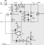
I have amended circuit diagram incorporating your suggestions...
Thanks a lot!
Ale
Attachments
I did assemble and test a very similar circuit with the same topology in the past. Found out that it is better to use an NPN transistor (e.g. MPSA 42) instead of the mosfet in place of M2 because of its lower cut-off current, but then of course you are limited by the Vce max which is 400v.
Also, the diode bridging the source and drain of the series regulator should stand the B+ - Vout(min) difference, hence an 1N4148 is not suitable here. A regular 1N4007 will do fine.
Lastly, the choice of the opamp is quite critical if you want to be able to regulate the output close to the bottom rail. You must make sure that under no circumstance the opamp will latch (look for bottom rail common mode latch free types). Speed is not so much of a problem for most practical purposes. The popular LM358 if a good choice too.
You might also want to play with a "speed up capacitor" in parallel to the upper half of the voltage sampling resistive divider. It decreases ripple at the output, but at the same time slows down transient response. A multi-step simulation will easily reveal a good tradeoff value for it.
Cheers
Hey izozaya, thanks for the input!
A bit late as I already etched the PCB.
If M2 behaves badly, I could use same NPN as Q1 as is a 1000V part, but that would require PCB hacking I will try as is.
M1 has a built in reverse diode. What diode are you referring to? D1?
I have added space for a 10pF speed up capacitor across R7. Haven't simulated it yet.
Regarding Op Amp, I'm a bit lost. I thought the LF351 could do a good job here...can you please expand?
Thanks
Ale
A bit late as I already etched the PCB.
If M2 behaves badly, I could use same NPN as Q1 as is a 1000V part, but that would require PCB hacking
I will try as is.M1 has a built in reverse diode. What diode are you referring to? D1?
I have added space for a 10pF speed up capacitor across R7. Haven't simulated it yet.
Regarding Op Amp, I'm a bit lost. I thought the LF351 could do a good job here...can you please expand?
Thanks
Ale
Hi,
You are right, the IRFGP40 has an internal reverse biased diode, which makes the one I was talking about redundant.
The problem with the cutoff current of M2 (between 0.1mA and 0.5mA depending on temperature) is that it will develop a voltage across the 940K resistor which is quite significant, and limits the Voutmax that you will get from the circuit. In a similar manner, this same cutoff current of M1 will impede that the output of the regulator swings down to 0v with open output or under high resistance loads. For instance, when trying to get 0v on a 100K load, the cutoff current of M1 will develop about 10-50v on the load. You can substitute M2 for an MPSA42, but you will have to stick with a power mosfet for the series pass element. I recall that there some inexpensive ones with Idss on the range of 10-50uA, which is one order of magnitude better than for the IRFGP40.
Real opamps are not perfect, and one of the deviations from the ideal component is that they do not work well when the inputs are close to the potential of either the top or the bottom rail. The consequences are various, from a lose of linearity to a hard latch up, where the output voltage latches to one of the rail values and stays there, more like a flip-flop. This is because current can flow from the input to the substrate, creating a sort of thyristor effect.
Some opamps are guaranteed to work well when the inputs are close to the bottom rail, others when close to the top rail, and others for both (aka rail to rail). Look in the datasheets for "common mode input voltage range" characteristics. In your design, when you want to regulate a voltage close to ground, both the reference and the sampling from the output will be at voltages close to ground (the bottom rail); this is why you need an opamp that behaves safely in this region.
For instance, the LF351 works well when inputs are close to the top rail (common mode input goes to V+), but does not work well when inputs go down to values close to bottom rail, which could cause the output to latch up in the regulator under discussion (with disastrous consequences for the load). The LM358, on the contrary, has a guaranteed common mode input that goes down to bottom rail, which is precisely what you need for the purposes of this regulator.
Cheers
Last edited:
Hey Izozaya,
Thanks for the detailed explanation.
Still am confused with the fact that the op amp wont sweep lower than 4.6V or so from about 14V. So when output voltage is at maximum (e.g. 614V), then the gate voltage is at around 4.66V. So in theory it shouldn't run the risk of latching up?
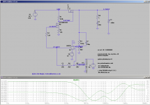
Also, have been playing with the speed up capacitor and output RC, and seems that can't get better response than the shown attached?
thanks again
Ale
Thanks for the detailed explanation.
Still am confused with the fact that the op amp wont sweep lower than 4.6V or so from about 14V. So when output voltage is at maximum (e.g. 614V), then the gate voltage is at around 4.66V. So in theory it shouldn't run the risk of latching up?
Also, have been playing with the speed up capacitor and output RC, and seems that can't get better response than the shown attached?
thanks again
Ale
Attachments
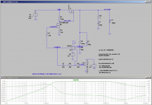
Yes, there is no risk of latch up when dialing for max Vout, as the voltages at the opamp inputs will be well within the input common mode range (from 0v to V+ - 1.5v). The output voltage that the opamp sets in order to try to make both inputs equal (4.66v in your simulation) is not important for this effect; it is only the (+) and (-) input voltages that matter.
That looks like a good amplitude and phase response. Should make a fine regulator.
That looks like a good amplitude and phase response. Should make a fine regulator.
Ok, so if in+ and in- is the only thing that matters then, in this configuration, the op amp will always try to match both inputs. So even if regulator output is at minimum (circa 4V) then the inputs of the op amp will be at around 30mV. In any occasion there will be a difference bigger than 5V and with the op amp supply being 24V, can't see how the latch up can occur? Can you help shedding some light?
So if this is not a problem then, I should be ok with LF351 then?
thanks!
Ale
So if this is not a problem then, I should be ok with LF351 then?
thanks!
Ale
Attachments
You are almost there.
The latch up would occur if you were using the LF351 in place of the LM358. When dialing the regulator for 0V at the output, then both inputs will be at a very low level (a few millivolts), and this is where problems begin because the common mode input of the LF351 does not go all the way down to the bottom rail. The LM358, on the other hand, is guaranteed to be latch free when the inputs are close or equal to the bottom rail (0v), and that is why it is a better option in this circuit.
The latch up would occur if you were using the LF351 in place of the LM358. When dialing the regulator for 0V at the output, then both inputs will be at a very low level (a few millivolts), and this is where problems begin because the common mode input of the LF351 does not go all the way down to the bottom rail. The LM358, on the other hand, is guaranteed to be latch free when the inputs are close or equal to the bottom rail (0v), and that is why it is a better option in this circuit.
Last edited:
Hang on, when dialling for low output, the LF351 will provide circa 24-1.5V and anything over 14V will force M1 close to cut off.
The bottom rail output limitation should occur when regulator output is maximum (first LTspice screenshoot) and is not needed to go below 4.6V and op amp input will never force them to go lower than 4.6V anyway.
I'm a bit thick here and can't see why the latching can occur. Perhaps I don't understand it properly....
Thanks
Ale
That is correct. When dialing for low output, the LF351 might latch, forcing its output to a high level, which will not be fatal in this design because that will put the series pass element in cutoff.
However, the problem is that the latch up condition will not disappear just by dialing up again; you will have to power off the circuit to resume normal operation. It is an inconvenient glitch rather than a fatal flaw. At least my design exhibited this behavior when using a TL081.
However, the problem is that the latch up condition will not disappear just by dialing up again; you will have to power off the circuit to resume normal operation. It is an inconvenient glitch rather than a fatal flaw. At least my design exhibited this behavior when using a TL081.
Ok. I will build and test and see if there is any latch up issue. Only issue is etching a new PCB or hacking the one made today. Not that I don't want to use the LM358, is just a pain where I am at the moment.
Thanks a lot for your advice. Will finish the boards next weekend and do some tests!
Thanks
Ale
Thanks a lot for your advice. Will finish the boards next weekend and do some tests!
Thanks
Ale
- Status
- This old topic is closed. If you want to reopen this topic, contact a moderator using the "Report Post" button.
- Home
- Design & Build
- Equipment & Tools
- 600V bench variable supply to test transmitting valves