Is there any advantage of connecting all three grids together for triode mode rather than the more common G1 = drive; G2 = anode; G3 = cathode connections?
G3 is anti-dynatron grid. Useless for triode. If you connect G2 to anode you get left-handed triode. If you connect G2 and G1 together you get right-handed triode.
G3 is anti-dynatron grid. Useless for triode. If you connect G2 to anode you get left-handed triode. If you connect G2 and G1 together you get right-handed triode.
Is there an advantage of left handed vs right handed when it comes to triode connected pentodes?
~Tom
Yeah, the gold/brass color 2-screw mounted with dark gray resistor cylinder in the middle are usually Dale RH or NH-series.
I posted my previous statement from work this morning. Now that I am at home I found the resistors. The gold resistor is indeed a Dale RH-250 rated for 120 watts. Big Brown is a "MEMCOR" rated for 500 Watts. One of the Dales that blew spit fire out of one end. DC can create some wicked arcs when things blow.
The KILL button is a really good idea.
I installed the KILL button when I built this lab 34 years ago. I instructed my wife and daughter to smack the button if there was ever an "incident" in this room whether I am home or not. Neither of them ever needed to use it, but I have whacked it a few times. The two in incidents recent memory both involved extracting obscene amounts of power from Petes red board. I have built a version of that board that pulls 1.2 AMPS from a 650 Volt supply in normal operation....producing 525 watts of tube audio. When an electrolytic shorted, it didn't vent. It instantly exploded with a loud bang leaving only a big black stain on the PC board and a stink in the room.
The red button came from a piece of industrial equipment. It is wired directly across the line voltage after the 15 amp bench breaker. It kills everything in the room except for what's on the UPS (main computer, TV and a light).
G3 is anti-dynatron grid. Useless for triode.
I never heard of left VS right hand triodes. Experiments with an EL34 revealed that some secondary emission effects can be seen with G3 tied to the plate which are not present with G3 tied to the cathode.
I posted a picture of the resistors. The tube is a 12AX7 included to show the size of these resistors. Big Brown will glow slightly red after 5 minutes of being plugged into the wall outlet. Thats about how long it takes to trip the breaker with an 8 ohm resistor and 160 watts worth of overhead light.
Attachments
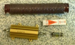
Dale RH-250 rated for 120 watts.
That's a pretty serious resistor. Years and years ago, I managed to get the gray resistive element of a 25 W Dale RH-25 (I think it was) to expand out of the aluminum case. I was using it as a dummy load on a power supply I built and I had it immersed in an oil bath for additional cooling. After about 30 minutes of dissipating way too much power, I noticed that the resistive element had expanded about 3~4 mm past the end of the aluminum case. The resistor was fine and reasonably close to its marked value by the time it cooled down. It never did recover to its original size, though.
~Tom
Big Brown came from Ebay. Actually there are 4 of them two 8 ohm, and two 15 ohm. They were cheap and there were no bids, but this was about 10 years ago. I plugged each one into the wall outlet to make sure they wouldn't go open when testing a big tube amp. That makes OPT's catch fire.
I have a friend that sells surplus, mostly military and NASA related stuff. I got a big box full of the 120 watt Dales from his metal scrap bin, for a few bucks. I won't trust them much beyond the rated power since I have blown two. Granted they saw a severe overload, but Big Brown eats this stuff and smiles!
I have a few Big Blacks around here somewhere. They are smaller.....maybe 100 or 200 watts and higher resistance. Good for stress testing big tube power supplies. They smoke, and glow red, but don't blow.
We have cleared all the "stuff" out of the rental warehouses and eliminated the rent payments. All the remaining "stuff" is now in this house, and I can't find anything!
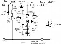
Ok, so here is a sand version I may go for before trying the valve one, as this may require a simple PCB and is an easy drop in the current supply.
So main pass mosfet is 2sk2613 (VDS=1000V, ID=8A). Here is the datasheet: http://www.google.co.uk/url?sa=t&rct=j&q=2sk2613&source=web&cd=1&ved=0CCAQFjAA&url=http%3A%2F%2Fwww.semicon.toshiba.co.jp%2Finfo%2Fdocget.jsp%3Ftype%3Ddatasheet%26lang%3Den%26pid%3D2SK2613&ei=0CtcUN-OJemn0QX2toBA&usg=AFQjCNF-UdYVdDjAxpNSiJiy20i_hUvIRQ
My question here is whether Q1 (PMBTA45) may need to withstand 600V in case of an output short despite it has the back to back zeners clamping VCE at 18V. If so, then the PMBTA45 won't be sufficient and I have the BUJ302A (1000V NPN transistor) at hand that should be ok. Will this be necessary? If not, I suppose that the PMBTA45 is not necessary here and a simple BC549 type should be ok?
Thoughts?
Ale
Attachments
i used Mpsa 42 cheap and effective. But whit the gate capacitance you added it will likely Blow
I would Toss the 4.7uf caps. they are going to unload through your transistor to ground if the short circuit protection kicks in
another thing is: Your not using any type of regulation. Consider using a string of Zeners to put the Potentiometer on a constant voltage (Lower than B+ !) or a constant Current like i did !
Go for a 250k 10 turn Bourns Pot By the way its going to be one of the least expensive parts on this build, and it gives real smooth voltage setting
and for a safety factor Fuse the AC line Fuse the DC line and add a 100ohms series resistor in B+ this can be a 10 watt type (0,075*100 = ) and it Will take most of the Heat when **** hits the fan
v4lve
for a safety factor Fuse the AC line Fuse the DC line and add a 100ohms series resistor in B+
Fusing the AC line is a given. Set the fuse current at just above the normal operating point, or at the minimum value that does not blow from the turn on surge.
Fusing a 600 volt DC line is not a good idea UNLESS you can find a fuse rated for 600 volt DC operation. An arc will self quench on AC. A DC fed arc (you know the little spark inside the fuse that happens when the link melts) will continue to burn and build up pressure until the fuse explodes. I found this out the hard way.
A big resistor in series with the B+ is a good idea, and is what I use to protect my mosfet. The resistor will eat the entire output of the power supply until a fuse or circuit breaker blows when the output is shorted. The resistance must be high enough to limit the current to less than the fets rating, and large enough to eat the power supply for a few seconds. No large capacitors can be placed after this resistor because they must discharge through the mosfet. I used a 15 ohm resistor. This limits the short circuit current to 40 amps, which is far better than a 600+ amp surge with 1 ohm fet. The resistor will see up to 9000 watts until the primary fuse blows. A small resistor will explode and possibly start a very destructive arc. Yes, been there too.
the AC secondary is a good idea too  fuse this at approx 1.5 times the DC value
if you want to go for quick and dirty try getting yourself 4* 5 watt 100 ohms
carbon comp resistors , parallel two and put them in series for 100 ohms , Put them in the B+ line
if your current limiter fails you. they will take the heat. they will smoke giving you a good indication the current limiting scheme has gone up in smoke
mind you though that you better separate them from anything flammable
you don't Need to use low resistance like 15 ohms you can even use 200 if you'd like but your going to **** away some B+ at higher currents
given that the design maximum is 75 milliamperes the 7.5 volts is acceptable whit a series resistance of 100 ohms
Best thing is to stabilize the voltage on the Pot. Whit zener diodes , Or constant current this will give the unit Good Line regulation i designed my unit whit this in mind 10% Headroom on the B+ is a good thing
also. don't forget to apply a reverse diode across the mosfet and the output of the regulator. you might want to hook up a capacitive load sometime ..
v4lve
fuse this at approx 1.5 times the DC value if you want to go for quick and dirty try getting yourself 4* 5 watt 100 ohms
carbon comp resistors , parallel two and put them in series for 100 ohms , Put them in the B+ line
if your current limiter fails you. they will take the heat. they will smoke giving you a good indication the current limiting scheme has gone up in smoke
mind you though that you better separate them from anything flammable
you don't Need to use low resistance like 15 ohms you can even use 200 if you'd like but your going to **** away some B+ at higher currents
given that the design maximum is 75 milliamperes the 7.5 volts is acceptable whit a series resistance of 100 ohms
Best thing is to stabilize the voltage on the Pot. Whit zener diodes , Or constant current this will give the unit Good Line regulation i designed my unit whit this in mind 10% Headroom on the B+ is a good thing
also. don't forget to apply a reverse diode across the mosfet and the output of the regulator. you might want to hook up a capacitive load sometime ..
v4lve
i used Mpsa 42 cheap and effective. But whit the gate capacitance you added it will likely Blow
I would Toss the 4.7uf caps. they are going to unload through your transistor to ground if the short circuit protection kicks in
Thanks v4love. You're right, I tried to combine the capacitor multiplier circuit with the current limiter using the transistor and missed this point.
I can add a zener string fed by a CCS and take the output of the potentiometer from here, is that what you are suggesting?
I have already a 1meg 3W pot, so will stick to this. 10turn pots over 200k are expensive and not sure if they are available over 3W for use them at 600V?another thing is: Your not using any type of regulation. Consider using a string of Zeners to put the Potentiometer on a constant voltage (Lower than B+ !) or a constant Current like i did !
Go for a 250k 10 turn Bourns Pot By the way its going to be one of the least expensive parts on this build, and it gives real smooth voltage setting
and for a safety factor Fuse the AC line Fuse the DC line and add a 100ohms series resistor in B+ this can be a 10 watt type (0,075*100 = ) and it Will take most of the Heat when **** hits the fan
v4lve
Yes, AC fuse will be there. Are you suggesting adding the 100ohm (10W) series before the mosfet, correct?
Thanks
Ale
the AC secondary is a good idea too
if you want to go for quick and dirty try getting yourself 4* 5 watt 100 ohms
carbon comp resistors , parallel two and put them in series for 100 ohms , Put them in the B+ line
if your current limiter fails you. they will take the heat. they will smoke giving you a good indication the current limiting scheme has gone up in smoke
mind you though that you better separate them from anything flammable
you don't Need to use low resistance like 15 ohms you can even use 200 if you'd like but your going to **** away some B+ at higher currents
given that the design maximum is 75 milliamperes the 7.5 volts is acceptable whit a series resistance of 100 ohms
Best thing is to stabilize the voltage on the Pot. Whit zener diodes , Or constant current this will give the unit Good Line regulation i designed my unit whit this in mind 10% Headroom on the B+ is a good thing
also. don't forget to apply a reverse diode across the mosfet and the output of the regulator. you might want to hook up a capacitive load sometime ..
v4lve
The 2SK613 MOSFET has a built in reverse diode...
I used a variant of this for a micro-processor controlled HV supply -- it's all incorporated into a Heathkit -- will develop it with a couple posts. You really don't want HV on a potentiometer if you can avoid it:
It's from "The Art of Electronics", and works beautifully.
An externally hosted image should be here but it was not working when we last tested it.
It's from "The Art of Electronics", and works beautifully.
i used Mpsa 42 cheap and effective. But whit the gate capacitance you added it will likely Blow
I would Toss the 4.7uf caps. they are going to unload through your transistor to ground if the short circuit protection kicks in
v4lve
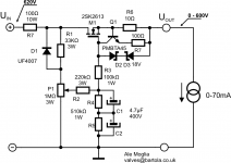
Looking back at the original desing and checking Merlin Blencowe's "Designing Power Supplies for Tube Amplifiers" I realised that Q1 should be placed straight at the M1 gate and have R3 (100K) between Q1 and the capacitor to limit discharge during current regulation...
Attachments
I used a variant of this for a micro-processor controlled HV supply -- it's all incorporated into a Heathkit -- will develop it with a couple posts. You really don't want HV on a potentiometer if you can avoid it:
An externally hosted image should be here but it was not working when we last tested it.
It's from "The Art of Electronics", and works beautifully.
This is a great idea. I can add a simple 15V supply feeding a 10T 100K pot on the gate of the first mosfet. Then add a current limiter to the pass mosfet and this looks like a simpler option...
Thanks
Ale
Maybe its simpler to use a transistor for that. Controlled by an op amplifier
However the function is inverse. when the transistor/mosfet draws current the output voltage goes down
so you might as well use an opamp for the job.
Opamp feeding a transistor whit the noninverting input on the output divider of the supply
the inverting on a pot fed by a reference.. Could work.
v4lve
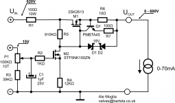
Here is a design update based on last recommendation. I have stf5nk100z mosfet at hand so can use that as the pass mosfet gate controlling device.
A 10T 100K pot is not expensive and will allow a smooth regulation of the output voltage. A 15V DC supply won't be hard to fit in the current chassis, so this looks like a promising alternative....
A 10T 100K pot is not expensive and will allow a smooth regulation of the output voltage. A 15V DC supply won't be hard to fit in the current chassis, so this looks like a promising alternative....
Attachments
there is nothing to compensate for an error . and i have a feeling the mosfet might shift .. Plus its not REGULATED.
all through a 600 volt pot is hard to find you have an alternative and that is getting one of those 1 pole 12 position switches and make a resistor decade out of that. feed it whit a CCS or use zeners..
Steps of 50 volt at a time that ain't half bad..
v4lve.
all through a 600 volt pot is hard to find you have an alternative and that is getting one of those 1 pole 12 position switches and make a resistor decade out of that. feed it whit a CCS or use zeners..
Steps of 50 volt at a time that ain't half bad..
v4lve.
- Status
- This old topic is closed. If you want to reopen this topic, contact a moderator using the "Report Post" button.
- Home
- Design & Build
- Equipment & Tools
- 600V bench variable supply to test transmitting valves