This is a Jim Williams design:
The new morgan jones shows how to implement depletion mosfets for protection -- so does the SuperTex website. (SuperTex also has an ap note for using the smaller depletion mosfets to protect instrumentation from inadvertent disasters.)
An externally hosted image should be here but it was not working when we last tested it.
The new morgan jones shows how to implement depletion mosfets for protection -- so does the SuperTex website. (SuperTex also has an ap note for using the smaller depletion mosfets to protect instrumentation from inadvertent disasters.)
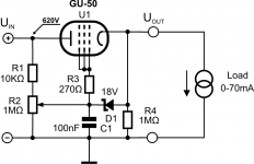
You can use here Gu-50 in "Right handed" mode, connecting all 3 grids together:
http://wavebourn.com/forum/download.php?id=491&f=7
http://wavebourn.com/forum/download.php?id=491&f=7
Allied has them at $ 9.32 still. the 2SK3527-01 with 21 amps is only about $2.35 no stock but the 2SK3528-01R is in stock with 160 watt dist. at $3.60 each .I believed this too......until I stumbled across these mosfets on the clearance page at Allied Electronics a couple of years ago. With a BIG (250 watt) 15 ohm resistor in the drain lead they will not blow into a direct short with 600 volts of supply. Of course they will be over dissipated in short order so a foldback circuit or a fuse is needed. For those who don't want to look through the data sheet, the important numbers are 600 volts, 600 WATTS, 43 AMPS of continuous drain current and 172 amps pulsed. They were clearance priced at $5 each when I got some. I don't know if they are still available. I haven't blown one yet.
I made a simple power supply using a large variac feeding a reverse wired 480VAC (2 X 240) to 120 VAC industrial control transformer rated at 1 KVA. There was a solid state FWB on each 240 VAC secondary making two 0-310 VDC variable supplies that could be wired in series or parallel. A smaller 120 VAC to 24 VAC industrial transformer with a small variac provided variable heater power. I used this for years, but there was no current limiting and several experiments ended in smoking or exploded parts.
I tried several post regulators that usually blew up to protect my experiment. That includes sweep tube pass devices. A huge current spike created by a momentary short takes out the metal link inside the tube that connects the cathode to the base pin. The Fuji fet survivied. A dead short across the output at maximum voltage would trip the bench breaker before blowing the fet (about 2 seconds). 60 amp peak currents will stil fry parts. That power supply was large and heavy, nearly 100 pounds. It has been dismantled.
I got a HP 0 to 600 volt 0 to 1.5 amp supply for big amp experiments. I am using that today, but it's current limiter is too slow to save parts. In fact this power supply has created some serious parts explosions.
Last edited:
I thought they eliminated all the old Fuji mosfets since they were all on their "excess inventory" list.
It seems that another of my old favorites is still stocked. The 2SK3675-01. It's not good for a big power supply, but makes a good source follower. Pair it with a triode tube in a darlington like configuration for the mother of all vacuum tubes. You get a triode with 195 watt and 7 amp capability. The key spec here is Crss = 8 pF.
The 2SK3524-01 is a smaller version, but no longer stocked. Maybe I bought them all. Good for direct coupled grid drive for A2 or AB2 operation (PowerDrive).
Note: None of the Fuji mosfets have integral zener gate protection. Wire a small (the smaller the better for low capacitance) 12 volt zener from gate to source to avoid blowing the gate in transient situations.....like a guitar amp cranked to 11.
You can use here Gu-50 in "Right handed" mode, connecting all 3 grids together:
http://wavebourn.com/forum/download.php?id=491&f=7
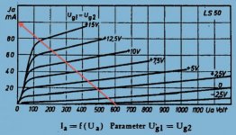
Actually, the title of the plot says that the screen and control grids (G1, G2) are wired together with the suppressor grid (G3) grounded.
~Tom
Actually, the title of the plot says that the screen and control grids (G1, G2) are wired together with the suppressor grid (G3) grounded.
Actually, in triode mode it does not matter where to put the suppressor grid. Try and compare. You can get some difference if add positive bias on it.
Last edited:
Hi Anatolyi,Actually, in triode mode it does not matter where to put the suppressor grid. Try and compare. You can get some difference if add positive bias on it.
Thanks for the suggestion, didn't think about the right handed option. It will be better to obtain more voltage span with my current design constraints I think.
Here is the circuit and looking at the loadline based on your curves, it looks like I won't need more than 15V of positive grid bias to sustain 70mA load at low output voltage.
So if replacing protecting diode by a 15-18V zener should ensure positive grid voltage is limited, but wouldn't this zener blow up if output is accidentally shorted?
Attachments
Sure, when shorted current will go also through 10K resistor and Zener, if voltage control pot is on maximum. 600V/10K = 60 mA. 36W on 10K resistor, 1 W on Zener. Total current will be the sum of this current and current through the tube. Current through the Zener will be less: part of it will go through grid-cathode. So you should worry now about 10k resistor and the pot.
Last edited:
So is worth using the 10k resistor as a protecting mechanism or is there a way of improving this any further?
I would add one more current limiting resistor, from pot to grid/Zener. Probably one more cathode follower (or source follower?) may be needed using smaller tube or small high voltage MOSFET if voltage drop on this resistor will be too high in normal operations' mode due to grid current.
those are some hefty mosfets 
I am using IRFPG50 or such 900 volts 6 amps for a 0-320volt supply, Its used in a tube tester and it needed to be short circuit proof
Raw B+ comes in at 340 vdc and ive added just a simple 100R resistor in the B+ line this limits potential short circuit current to 3.4A Well whitin SOA
The current source adds good line regulation. cheap and effective

you can change the 100K resistor for a higher value. the zener is still there to protect the IC against any over voltage (differential)
V4lve.
ive been playing whit the idea of making a simple short circuit Cutout.
What about a low side current shunt that fires a thyristor that in turn latches a relay that turns B+ off.
Interrupt the Relay coil supply and you will reset the cutout..
I am using IRFPG50 or such 900 volts 6 amps for a 0-320volt supply, Its used in a tube tester and it needed to be short circuit proof
Raw B+ comes in at 340 vdc and ive added just a simple 100R resistor in the B+ line this limits potential short circuit current to 3.4A Well whitin SOA
The current source adds good line regulation. cheap and effective
you can change the 100K resistor for a higher value. the zener is still there to protect the IC against any over voltage (differential)
V4lve.
ive been playing whit the idea of making a simple short circuit Cutout.
What about a low side current shunt that fires a thyristor that in turn latches a relay that turns B+ off.
Interrupt the Relay coil supply and you will reset the cutout..
I would add one more current limiting resistor, from pot to grid/Zener. Probably one more cathode follower (or source follower?) may be needed using smaller tube or small high voltage MOSFET if voltage drop on this resistor will be too high in normal operations' mode due to grid current.
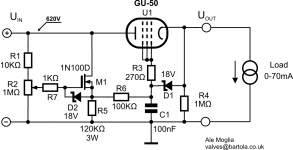
Ok, here it comes: a bit of sand to the circuit
I can use an IXYS IXTP01N100D as I have some. Perhaps not the ideal MOSFET here but should do the job. A bit puzzled as to how bias this MOSFET when the operating point will vary from 0 to 600V
So when choosing R5 I looked at worst case scenario (i.e. 600V at the output of the follower or across R5). My question here is whether when operating at low voltages the current across the MOSFET will be too low for proper operation? Other key question is the value of R6. The GU-50 g2 current can be as high as 20mA, but I'm blind as to how much grid current can go through the valve in right-handed mode. Anyone has any chart on this? I think the balance of R6 is between grid current and a high value to limit the current through output zener if the output is accidentally shorted...
Thanks for the help!
Attachments
An externally hosted image should be here but it was not working when we last tested it.
Geez! The BD139 is good for only 80 volts!
But if you'd consider using a higher voltage device, your suggestion micGt work.
Regards!
Actually, in triode mode it does not matter where to put the suppressor grid. Try and compare. You can get some difference if add positive bias on it.
I believe that. I was merely translating the title of the plot you showed, that's all.
Is there any advantage of connecting all three grids together for triode mode rather than the more common G1 = drive; G2 = anode; G3 = cathode connections?
~Tom
Raw B+ comes in at 340 vdc and ive added just a simple 100R resistor in the B+ line this limits potential short circuit current to 3.4A Well whitin SOA
3.4 A, 340 V --> >1100 W dissipated. This amount of power is shared between the MOS and the resistor. I suspect one of them will lose and blow up. Though, I suppose a 250 W chassis mounted resistor could conceivably survive a 1 kW pulse for long enough to allow an electronic shut-off to kill the mains. It would still have to dissipate whatever energy is stored in the reservoir caps, though.
This is why high energy supplies are difficult to design...
I suggest downloading some service manuals from the pros and see how they do it. Personally, I'd page through some of the HP service manuals. You can download them from Agilent directly - www.agilent.com.
~Tom
I suppose a 250 W chassis mounted resistor could conceivably survive a 1 kW pulse for long enough to allow an electronic shut-off to kill the mains.
A 1 KW pulse, probably. I have a big box full of low value 250 watt chassis mount resistors, the big gold anodized aluminum cased units (Dale?). I blew two of them with my variac adjustable supply. Short circuit dissipation is about 24 KW.
My bench has a master breaker at 15 amps and a big red KILL button. That limits the fun at 1.8 KW. I have blown the breaker a few times with a big amp under "normal" but extreme operating conditions, and several times by accident. Yes, I have needed to smack the big red button too!
I got a big brown glass coated ceramic wirewound resistor off of Ebay, exact wattage and manufacturer unknown. It is about a foot long and 1.5 inches in diameter. It survived the dead short until the main bench breaker blows test.....several times. I have two similar resistors at 8 ohms each that I use for testing serious amplifiers.
3.4 A, 340 V --> >1100 W dissipated. This amount of power is shared between the MOS and the resistor. I suspect one of them will lose and blow up. Though, I suppose a 250 W chassis mounted resistor could conceivably survive a 1 kW pulse for long enough to allow an electronic shut-off to kill the mains. It would still have to dissipate whatever energy is stored in the reservoir caps, though.
~Tom
The thing is that i put the resistor there to make sure the mosfet can survive the initial short circuit pulse. the mosfets internal resistance is about 5 ohms.
Imagine what kind of overcurrent that creates
On overcurrent the transistor latches on and forms a divider between the 100k resistor and load resistance. the gate will be positioned at the low end of the divider , Bringing the gate down quickly
i have put a 4.7 ohms current sensing resistor for the transistor a voltage drop greater than 0.6 volts will turn the transistor on (Typical for a Si device) this works out at about 130 millamperes of current
0.13 *340 =44 watts of heat the transistor is on a decent heatsink Whit forced air cooling
the nice bit about this circuit is that it acts like a voltage source and on overcurrent it acts like a current source
v4lve
I have a big box full of low value 250 watt chassis mount resistors, the big gold anodized aluminum cased units (Dale?). I blew two of them with my variac adjustable supply. Short circuit dissipation is about 24 KW.
Yeah, the gold/brass color 2-screw mounted with dark gray resistor cylinder in the middle are usually Dale RH or NH-series. They're pretty darn rugged. I'm impressed that you managed to blow one of those. Impressed, but knowing you, not entirely surprised....
My bench has a master breaker at 15 amps and a big red KILL button.
The KILL button is a really good idea. I have often thought of installing one... Though thus far the 5 A fast fuse in my variac has provided enough protection against big blowouts.
i have put a 4.7 ohms current sensing resistor for the transistor a voltage drop greater than 0.6 volts will turn the transistor on (Typical for a Si device) this works out at about 130 millamperes of current
0.13 *340 =44 watts of heat the transistor is on a decent heatsink Whit forced air cooling
44 W should be fine - even without forced air cooling if just for a short while. That just wasn't what I interpreted from your post that mentioned the 3.4 A short-circuit current.
~Tom
Ok, here it comes: a bit of sand to the circuit
I can use an IXYS IXTP01N100D as I have some. Perhaps not the ideal MOSFET here but should do the job. A bit puzzled as to how bias this MOSFET when the operating point will vary from 0 to 600V
Other key question is the value of R6. The GU-50 g2 current can be as high as 20mA, but I'm blind as to how much grid current can go through the valve in right-handed mode. Anyone has any chart on this? I think the balance of R6 is between grid current and a high value to limit the current through output zener if the output is accidentally shorted...
Thanks for the help!
Thanks all for various suggestions and sharing your ideas, but as I said on my first post, I'm looking at achieving this without significant rework or additional parts. Appreciate your input and knowledge here
- Status
- This old topic is closed. If you want to reopen this topic, contact a moderator using the "Report Post" button.
- Home
- Design & Build
- Equipment & Tools
- 600V bench variable supply to test transmitting valves