Continuation
Having found the parallel output 'sucks' 😡 I went ahead and tried Abraxalito's output concept of eliminating the pull-up current sources within the TDA1543:
Well, the signal improved dramatically, from somewhat muddy to rather clear.
I still have to make a distortion analysis but the results so far are very good.
The triggering is external and with 44 kHz.

And then:
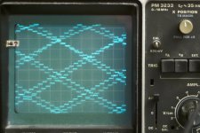
The top signal which is bit clearer is 470 ohms, the one just beneath it is 820 ohms.
The result looks very clean. Clear steps. Imho improved from having Vref connected to ground.
With the first setting (1K2 ---> GND) the current into the 470 ohms was 2,11 mA, and setting the virtual earth to another voltage (+/- 0,05 V) did not change the current.
With the floating Vref pin, the output current was 1,21 mA, also independent of the virtual earth voltage setting.
Output on 470 ohm = 280 mV and to 820 ohms is 360 mV.
The source is a Philips CD210, which is old and the I2S is taken from the SAA7220. Taking the bare signal before the SAA7220 is a next step of course,
Having found the parallel output 'sucks' 😡 I went ahead and tried Abraxalito's output concept of eliminating the pull-up current sources within the TDA1543:
- the output resistors not to earth but floating, tried 470 and 820 ohms
- and attached to a virtual earth - created with a TL431 shunt
- the shunt being set at 3,80 V
- and the Vref pin being connected with 1k2 to earth
Well, the signal improved dramatically, from somewhat muddy to rather clear.
I still have to make a distortion analysis but the results so far are very good.
The triggering is external and with 44 kHz.

And then:
- and the Vref pin being DETACHED


The top signal which is bit clearer is 470 ohms, the one just beneath it is 820 ohms.
The result looks very clean. Clear steps. Imho improved from having Vref connected to ground.
With the first setting (1K2 ---> GND) the current into the 470 ohms was 2,11 mA, and setting the virtual earth to another voltage (+/- 0,05 V) did not change the current.
With the floating Vref pin, the output current was 1,21 mA, also independent of the virtual earth voltage setting.
Output on 470 ohm = 280 mV and to 820 ohms is 360 mV.
The source is a Philips CD210, which is old and the I2S is taken from the SAA7220. Taking the bare signal before the SAA7220 is a next step of course,
and I should mod the player with a stable Tent clock - that would improve the stability enormously too probably.
then I will attach the XMOS USB-I2S card.Today I tested the distortion components, a single chip with 820 ohms connected to the Vbias of 3,80 V.
Clear components without much 2nd, 3rd visible without output filter; Then with the filter of 1 mH/1000 pF-2,7 nF:
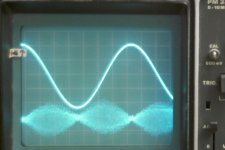
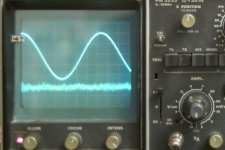
The filter clears all 'steps'.
When looking on the output resistor directly but filter attached there is a slight ringing; this disappears with an added filter on the front of 1,5 nF:
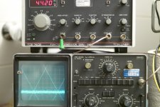
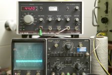
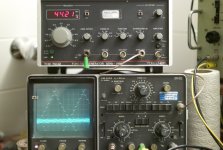
How to get these views? It is quite a bother to set up.
Now a question:
so far so good.
The power supply gets noise from 0,00 mV -80 dB signal to 2,5 mV as the playing of 0 dB signal starts.
Clear components without much 2nd, 3rd visible without output filter; Then with the filter of 1 mH/1000 pF-2,7 nF:


The filter clears all 'steps'.
When looking on the output resistor directly but filter attached there is a slight ringing; this disappears with an added filter on the front of 1,5 nF:


How to get these views? It is quite a bother to set up.
- timebase 50 uSec
- sensitivity 20 or 50 mV/cm
- Magnifier *5
- external timebase 44,20 kHz, finetune untill the result apears as a mesh.

Now a question:
[*]Does clearing the sine of the steps take away the images?
so far so good.
The power supply gets noise from 0,00 mV -80 dB signal to 2,5 mV as the playing of 0 dB signal starts.
Essentially, yes clearing the steps is the same as filtering out the images. Hard to do as the frequency nears 20kHz though, easier at 1kHz.
The output is now about 380 mV at 0dB signal which means that it needs to be amplified about 5 times to get the nominal 2,1 V RMS (which corresponds to 700 mV RMS line signal - the extra 10 dB is overhead of the CD format).
My pondering:
My pondering:
- Is it possible to make the filter that is used standard by Philips but make it into a version with 5* gain? Instead of connecting the output to the -, connect with a voltage divider ? The standard filter is designed for 4* OS. . .
- is it possible to have upsampling without interpolation or is this a worthless trick as the image without interpolation would still be centered at 44 kHz?
- interpolation creates extra bits doesn't it. So when the interpolated 16 bits signal that grows to 18 bits or more is fed to a 16 bits DAC again, some basic information is gone?
Last edited:
Yes you can have a digital filter with digital gain but it won't get you any more analog output, it'll just clip.
And yes, quite possible to have upsampling with different forms of interpolation, or none. This latter option I've tried - its called 'RTZ' (return to zero). Works fine but for the reduced output level - but for me NOS sounded better. Zero order hold interpolation won't shift the images to a higher frequency but RTZ does.
And yes, quite possible to have upsampling with different forms of interpolation, or none. This latter option I've tried - its called 'RTZ' (return to zero). Works fine but for the reduced output level - but for me NOS sounded better. Zero order hold interpolation won't shift the images to a higher frequency but RTZ does.
I thought RTZ was a DAC output format? It better approximates an impulse so reduces the HF droop sinc response seen with normal DAC.
Yep that's my understanding too - is it incompatible with my earlier post? RTZ can be seen as an 'output format' or as upsampling where the 'interpolated' samples are zeroes.
It rather stretches the meaning of upsampling!
My understanding is that RTZ does not move images, as the sampling frequency remains the same, but it does reduce or eliminate the HF droop on the wanted audio components.
My understanding is that RTZ does not move images, as the sampling frequency remains the same, but it does reduce or eliminate the HF droop on the wanted audio components.
Thanks for pointing this out about the images not moving, I agree now they don't. I think my confusion on this point arose when I implemented this in conjunction with an FIR filter to attenuate the images centred at 44k1. A 50% RTZ 44k1 signal is equivalent to an 88k2 signal with every other sample muted - this is how upsamplers work typically. The SAA7220 that Al's referred to does its 4X upsampling by stuffing (literally called zero-stuffing) 3 zeros in after each sample from the 44k1 input stream, creating a 75% RTZ signal which is then run through the FIR filter to attenuate the images upto the Nyquist of the 4X rate (88k2).
Interesting article on an RTZ DAC here - http://www.tnt-audio.com/clinica/convertusdecima_e.html
Interesting article on an RTZ DAC here - http://www.tnt-audio.com/clinica/convertusdecima_e.html
Last edited:
Yes, zero-stuffing is often the first stage of upsampling but it doesn't really change the sample rate except in a theoretical sense. These two signals are essentially identical:
44.1k audio, with 50% RTZ
44.1k audio plus image, sampled at 88.2k with first-order hold
I have from time to time thought about how to add RTZ to a simple NOS DAC by adding a clamp to the output. Never came up with a good method, though.
44.1k audio, with 50% RTZ
44.1k audio plus image, sampled at 88.2k with first-order hold
I have from time to time thought about how to add RTZ to a simple NOS DAC by adding a clamp to the output. Never came up with a good method, though.
You investigated RTZ for the purpose of flattening the sinc droop? If the DAC's not very glitchy then sending it a zero sample in between each and every 44k1 sample will do it, at the expense (as reported in the article I linked) of a 6dB reduction in output level. The challenge of designing the external clamp is in bettering the glitchiness of the DAC itself.
i dare say better than active sinking for floating vref is connecting it to the center tab of a 1:1:1:1 transformer in a setup like the one below.
ecp.cc
just one pin per transformer.
before this no matter what method i tried, feeding v to bias resistors never sounded 'natural', but vref straight to center tap gets me close to the sound i was hoping for... which is, 1704 killer 😀
i say close because when vref is lifted and 1543 loses that blanket of distortion, the sound it reveals is always a bit grating and ordinary, at least to me. in fact... i think i'll resort back to vref grounded setup and swap out the salas shunt for lm317. 1543 doesn't deserve it hehe.
Last edited:
This is what I meant, outside of digital domain, in analogue part: a post-I/V filter with gain.
View attachment 371863
Though I don't generally like opamps, specifically not for I/V here it might work . . . with some gain even.
Oops.
I found out that this is not OK because the feedback path needs to be reduced with the gain: smaller C and hence larger L, both with the amplification factor.
And the return path of the differential needs to float with a capacitor to earth (if the input has DC - and it will have if it is connected to an TDA1543 without a cap in between).
i dare say better than active sinking for floating vref is connecting it to the center tab of a 1:1:1:1 transformer in a setup like the one below.
ecp.cc
just one pin per transformer.
before this no matter what method i tried, feeding v to bias resistors never sounded 'natural', but vref straight to center tap gets me close to the sound i was hoping for... which is, 1704 killer 😀
i say close because when vref is lifted and 1543 loses that blanket of distortion, the sound it reveals is always a bit grating and ordinary, at least to me. in fact... i think i'll resort back to vref grounded setup and swap out the salas shunt for lm317. 1543 doesn't deserve it hehe.
This connecting of Vref implies that the Vdd is 5 volts?
i think i'll resort back to vref grounded setup and swap out the salas shunt for lm317. 1543 doesn't deserve it hehe.
I looked on my breadboard -100 uF locally and a 20 cm twisted wire to a 431-series regulator with 0,0mV noise, that when the music is playing there is about 0,5 mV noise on the PS. So a local Salas with sense wires is a good choice.
Needed however?
The TDA1543 can be beautiful at high volumes while even fed by 317's. . . if properly decoupled.
true that. 😉
sorry for derailing the subject but do you know any dc null circuit for the chip? i tried to mate sen i/v to 1543 today and of course it didn't work because of the dc offset from the chip. sen can't have any dc offset on it's input.
sorry for derailing the subject but do you know any dc null circuit for the chip? i tried to mate sen i/v to 1543 today and of course it didn't work because of the dc offset from the chip. sen can't have any dc offset on it's input.
true that. 😉
sorry for derailing the subject but do you know any dc null circuit for the chip? i tried to mate sen i/v to 1543 today and of course it didn't work because of the dc offset from the chip. sen can't have any dc offset on it's input.
The SEN has to be made single power supply, so a virtual reath has to be made. If you have 5 volts then as far as I see it you could connect the gates to pin 7 (Vref) and with that the pin gets its name again.
I think that this also works at some higher voltages but I'm not sure where this ends.
The output is taking 1,2 mA (so into pin 6,8) in my config by the way. The SEN will be a bit off-balance but that could be balanced by a teeny weeny little resist in the bottom FETs if you really go for the lowest distortion, probably.
I will try similar but with one 2SK1078 on the top. It provides an output without any ringing for the staircase - I have tested that on my 1541. This single 2SK1078 has a transconductance of 68 mA/V. Darn low resistance . .
thanks al,
realized this morning that i hadn't wired any resistors on sen :embarrassed:
i wired both channels of sen to a single salas shunt module, though i knew separate supply was recommended (but was it a must?) salas shunt doesn't like any offset, and will not even activate in many cases such as when i tied post reg for 1543 to it.
also found this neat little trick from way back when.
http://www.diyaudio.com/forums/digital-source/22612-active-current-source-tda1543.html
- Status
- Not open for further replies.
- Home
- Source & Line
- Digital Source
- TDA1543 semi-parallel solution
