Does anyone have any measurements of improvements when Vref is left o/c? If the internal current mirror has a flaw then this ought to show up in noise or distortion tests.
I tested awith Vref open with a Vdd of 7 volts,
- with the chip I tried there was no output, that one chip did not fire up,
- and that chip died, because when I connected to a resistor it did not come above 0,9 volt on the pin.
- . . could be the chip was dead on arrival, but should I try a second time with another chip?
Could well be that at Vdd of 5V this does work . .
But I tested and there was no output; voltage on pin 7 was 2,25. Tried various output values (pot).
So I'm puzzled at what the mod of leaving it open really is

Last edited:
If you leave Vref o/c then you must make proper arrangements for Vout such as a potential divider - you can't just put a resistor to ground as you have no balancing current from the internal source. TDA1543 normal output current is a data-controlled sink, not a source. That is why we normally need to use the internal current source to balance it.
No experience of using 1543 with active I/V, no. I'm firmly converted to the passive I/V camp now though I do sometimes use a common-base transistor if I'm after a tad more output compliance...
abraxalito, saw your anti-imaging filter. Nice!
What is the approximate output impedance of the TDA1543, dynamically? This is for calculating a filter that would start with R/C then L/C to obtain an 18 dB/oct LPF that is simple;
for instance.
I like you latest filter, looks a bit complicated even though I have an L-meter.
- [internal resistance+external resistance, aimed at totaling 120 ohms]/27nF = approx 46 kHz
- 1mH/12nF = approx 45 kHz
So my question is: what series output resistor to add to aim at e.g. 120 ohms?
abraxalito, saw your anti-imaging filter. Nice!
Thanks, nice to know someone is appreciating my blog
What is the approximate output impedance of the TDA1543, dynamically?
I reckon its effectively the I/V resistor's value as its presumably an open-collector whose output impedance will be an order of magnitude or more higher than the I/V resistor.
I like you latest filter, looks a bit complicated even though I have an L-meter.
The one I've been playing with most recently is a single inductor value filter, so no L meter is called for as it can work with not-so-very-precise values available off the shelf. The most recent incarnation of this uses Coilcraft 3.3mH SMT coils about 6mm square, 8 per channel. If you'd like the schematic I'll put it up on the blog. Its load impedance is 270R but if you want to work into a different impedance, just scale the inductor values linearly with the chosen load resistance. Say to work into 120R the inductors would become 12/27 * 3.3mH = ~1.5mH. If you don't feel you need the steep slope offered by 8 inductors you can always shorten the length as its using repeated stages which are identical.
TDA1543 USB dongle!
A dongle being a little interface with cords, that is what I envision now:
one cable to the power supply and output cinch [CAT6 cable], one cable for USB, as short as possible.
Very compact is possible.
This is how it can look with an XMOS I2S card:
in the little box,

where one side will have a little USB cord dangling (dongling?) out - so this little box goes close to the PC;
A closeup of the card/card interface, with possible output capacitors to the right:

Resistors not attached in this concept.
A dongle being a little interface with cords, that is what I envision now:
one cable to the power supply and output cinch [CAT6 cable], one cable for USB, as short as possible.
Very compact is possible.
This is how it can look with an XMOS I2S card:
in the little box,
where one side will have a little USB cord dangling (dongling?) out - so this little box goes close to the PC;
A closeup of the card/card interface, with possible output capacitors to the right:
Resistors not attached in this concept.
I have 4 chips now parallel each with 1700 Rout; so it is effectively 425 ohms.I reckon its effectively the I/V resistor's value as its presumably an open-collector whose output impedance will be an order of magnitude or more higher than the I/V resistor.
Then I tap each chip with a 200 ohms resistor to a common point with a capacitor of about 6,8 nF. This gives 49 kHz and is intended to be the first pole. I use this summing resistor to keep the outputs somewhat independent in DC level. The four chips differ several tens of mV on the output.
The problem is I can't measure in anyway what the LPF frequency is . . .
For me the 8 steps steepness is a bit overdone but it depends on using NOS or (some) OS - and on pre/amplifier and speakers.The one I've been playing with most recently is a single inductor value filter, so no L meter is called for as it can work with not-so-very-precise values available off the shelf. The most recent incarnation of this uses Coilcraft 3.3mH SMT coils about 6mm square, 8 per channel. If you'd like the schematic I'll put it up on the blog. Its load impedance is 270R but if you want to work into a different impedance, just scale the inductor values linearly with the chosen load resistance. Say to work into 120R the inductors would become 12/27 * 3.3mH = ~1.5mH. If you don't feel you need the steep slope offered by 8 inductors you can always shorten the length as its using repeated stages which are identical.
I want to go at least 2-times Interpolation and Oversampling in the PC, so my case is more like the one on the right than on the left:
View attachment 370420
The diagram: The shapes on the right are the images we want to reduce.
For me I think and LFF or 45 kHz of 18 dB in total is rather good as the images would be at 160 kHz if I understand it correctly. And I have some stock 1 mH chokes at hand
You're right that going for 2X OS you don't need nearly so steep a filter as for NOS. I got an 'invalid attachment' message so can't see your piccy but with 2X OS your images will start around 2*fs-20k = 68kHz. At a guess a 2 inductor filter should be sufficient. I could have a stab at designing it for you if you tell me what the DCR of your 1mH inductors is.
You're right that going for 2X OS you don't need nearly so steep a filter as for NOS. With 2X OS your images will start around 2*fs-20k = 68kHz. At a guess a 2 inductor filter should be sufficient.
I have tried by trial and error but just 1mH/15nF has too low a Fc, even with 10 nF it is (sweep). The attenuation at 20 kHz is already 1 dB, this is not a wanted outcome.
Great. My 1 mH chokes have a DCR of 12 ohm. I also have 27 mH with a DCR of 170 ohm. The output impedance after the DACs is 507 ohm.I could have a stab at designing it for you if you tell me what the DCR of your 1mH inductors is.
Picture:

My gut feel is that with 12ohms DCR your inductors aren't high enough Q but I might have a play. My 3.3mHs are only about 8ohms and even with them there's some droop, but with fewer inductors there's less demand for high Q. Do you know what kind of core they have? Ferrite or iron dust?
My gut feel is that with 12ohms DCR your inductors aren't high enough Q but I might have a play. My 3.3mHs are only about 8ohms and even with them there's some droop, but with fewer inductors there's less demand for high Q. Do you know what kind of core they have? Ferrite or iron dust?
No idea what the core is, they are green and small. Like a small resistor.
I have some pictures:
I set the triggering to 44 kHz and this gave me a frame per sample, sort of, anyway, the time domain is spread out very much. I once had triggering even at a higher sample rate, showed the clear steps.
My simple simple filter: one section or an added second section. Just breadboarding

The first picture shows the result with just 1n5 (left trace) and 1n5/1mH/2n7 (the right of each pair). The latter is much more relaxed - thinner, less HF trash.

Then I looked at the output with the distortion meter, that brings all debris to the forefront.
The first picture is with 1mH/2n7; the second is with a higher filter of 1mH/10 nF.


In the latter a glitch is visible
With four chips there is a higher chance for one to be off from perfect. And of course I bang around quite a bit with them (like soldering while I forget to turn off the power.. )
Because of that glitch I will in my next variant go for a single chip that I can handpick!
I set the triggering to 44 kHz and this gave me a frame per sample, sort of, anyway, the time domain is spread out very much. I once had triggering even at a higher sample rate, showed the clear steps.
My simple simple filter: one section or an added second section. Just breadboarding
The first picture shows the result with just 1n5 (left trace) and 1n5/1mH/2n7 (the right of each pair). The latter is much more relaxed - thinner, less HF trash.
Then I looked at the output with the distortion meter, that brings all debris to the forefront.
The first picture is with 1mH/2n7; the second is with a higher filter of 1mH/10 nF.
In the latter a glitch is visible
With four chips there is a higher chance for one to be off from perfect. And of course I bang around quite a bit with them (like soldering while I forget to turn off the power..
)Because of that glitch I will in my next variant go for a single chip that I can handpick!
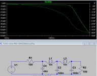
Here's a first stab - its assuming the 1mHs have no frequency dependent losses - a major assumption. The working impedance is 100R, set by the desired corner freq and your inductors.
Thanks, looks nice and comprehensive, it is a real filter
- but as I was planning a capacitor out of 0,4 uF this can't be used;
and with this filter I would need a very big cap or a buffer stage - it reduces the signal with 6 dB (100 ohms at input and 100 ohms at the end).
I have experimented already with bridging the inductor with 4,7 nF and this gave a nulling (well, not completely) at about 85 kHz, not bad for a quicky experiment and a first shot.
And this retains the high level signal of about 1 V RMS.
Glitches in TDA1543
In my previous post of distortions I posted a picture that showed some glitches in the overall (combined) output.
There is quite a difference! The outcome deviates and each chip has a different signature.
There is also difference per chip between L and R. So here my samples.
Chip I R and L, code Thailand N51328


This shows glitches in L.
Chip II R and L, code Thailand N51328


Doesn't look bad.
Chip III R and L , code 22744 stamped Taiwan on back


Second shot, pulled out chip and reinserted.


In first R is having some trouble with the tops of the 0 dB sine; L has some trouble and spreading the spectrum. Second attempt: looks quite good after all.
Chip 4 R and L , code 26764, stamped Taiwan on back


In L there are glitches.
Conclusion
There is quite some difference in chips!
I becomes clear to me that adopting a massive parallel approach has its drawbacks;
but a filter can be made easier because of the low impedance that follows from the paralleling (Rtot out is 425 ohms with Rout 4*1K7).
Have to find replacements for these 'faulty' chips.
In my previous post of distortions I posted a picture that showed some glitches in the overall (combined) output.
I have each chip with 1k7 out and I have 1k2 connected to Vref (so no current source). Source: 1000 Hz 0 dB from Pedja. Output tapped from SAA7220 so 4*OS.
Because I suspect differences in chips, I took a look at the distortion of the four separate chips I have.There is quite a difference! The outcome deviates and each chip has a different signature.
There is also difference per chip between L and R. So here my samples.
Chip I R and L, code Thailand N51328
This shows glitches in L.
Chip II R and L, code Thailand N51328
Doesn't look bad.
Chip III R and L , code 22744 stamped Taiwan on back
Second shot, pulled out chip and reinserted.
In first R is having some trouble with the tops of the 0 dB sine; L has some trouble and spreading the spectrum. Second attempt: looks quite good after all.
Chip 4 R and L , code 26764, stamped Taiwan on back
In L there are glitches.
Conclusion
There is quite some difference in chips!
- only chip II and III are acceptable.
- The glitches prohibit use of chips I and IV.
I becomes clear to me that adopting a massive parallel approach has its drawbacks;
but a filter can be made easier because of the low impedance that follows from the paralleling (Rtot out is 425 ohms with Rout 4*1K7).
Have to find replacements for these 'faulty' chips.
The good thing about those plots is that the dominant distortion is 2nd in all of them. The bad thing is that it always seems to be the same polarity so won't cancel when you parallel. My guess is that this is caused by the much larger than spec output voltage testing the linearity of the output current generators.
There is some 3rd too, but this looks more random between chips so will partly cancel in parallelling.
There is some 3rd too, but this looks more random between chips so will partly cancel in parallelling.
The good thing about those plots is that the dominant distortion is 2nd in all of them. The bad thing is that it always seems to be the same polarity so won't cancel when you parallel. My guess is that this is caused by the much larger than spec output voltage testing the linearity of the output current generators.
There is some 3rd too, but this looks more random between chips so will partly cancel in parallelling.
Hey,
yes you make me think of the following: have two chips on one end of the distortion spectrum by setting Rref and two on the bottom, assuming this would flip the distortion direction.
I like the positive going 2nd harmonic by the way and if I understood it right, Nelson Pass also suggests this setting with the F5 turbo. In synch with the positive pulse sounds more natural. In Holland, Peter van Willenswaard also commented on this finding long ago and speculated that this might come because of the natural way voices work, traditional speakers too. So is is just taste at the end, not measurements.
Yes I agree that I choose the larger than specs voltage because of aiming for dominant second harmonics.
End of the paralleling saga?
After I had tested all chips separately, and replacing the chips with the slight defects, I connected them again, and lo and behold, the summing of outputs again showed an increase of the HF residue - and looks like doubled from the individual footprints.
I conclude that paralleling is not a good idea.
\
Of course with tweaking the HF filter I can clear the HF spectrum of the images .
albert
- Status
- This old topic is closed. If you want to reopen this topic, contact a moderator using the "Report Post" button.
- Home
- Source & Line
- Digital Source
- TDA1543 semi-parallel solution