Played around a liitle more this morning to try to reduce the staircase noise comming from the PCM1704 to the input of the AD844 (remember mine is straight in), so I put a 1000pf to ground on pin 2 (input) (ala Pedja's TDA1541 circuit) to see what effect it had on the noise, by my calculations with the 1k output impedance of the PCM1704 then a 1000pf to ground this should filter -3db @160khz? But it did nothing, nada, zip to the staircase noise noise or amplitude. I didn't want to go larger with the cap, as I feared taking out the pcm1704.
Cheers George
Cheers George
Last edited:
Played around a liitle more this morning to try to reduce the staircase noise comming from the PCM1704 to the input of the AD844 (remember mine is straight in), so I put a 1000pf to ground on pin 2 (input) (ala Pedja's TDA1541 circuit) to see what effect it had on the noise, by my calculations with the 1k output impedance of the PCM1704 then a 1000pf to ground this should filter -3db @160khz? But it did nothing, nada, zip to the staircase noise noise or amplitude. I didn't want to go larger with the cap, as I feared taking out the pcm1704.
Cheers George
Yep. But of course it is not the 1k OP Z of DAC that you use to size the cap but the -IP Z- of the IV. As such the cap will end up being huge,
it will cause HF noise multiplication (of the IV not DAC) through the IV, and
decrease it's linearity.
No free lunch George. I've done all that stuff and much more. If you really
want a LPF -before- the I-V, try an air core inductor between dac and
IV then a cap to gnd directly at DAC OP. Given physical constraints of the
size of inductor, the LPF frequency will be very high. To get this right,
prolly need to simulate it.
Why do you need to filter the DAC beyond simple OP LPF? What is it you are
hearing?
Z
Why do you need to filter the DAC beyond simple OP LPF? What is it you are
hearing?
Z
It's just truly amazing as it is, but I cannot help myself I have to experiment, and I thought if I could lower the staircase noise before the AD844, it could lessen the duties that the I/V stage has to perform, instead of first getting filtered at TZ output.
I wonder then why Pedja put a 1.5nF to ground on the TDA1541 AD844 circuit.
Cheers George
Yep. But of course it is not the 1k OP Z of DAC that you use to size the cap but the -IP Z- of the IV. As such the cap will end up being huge,
it will cause HF noise multiplication (of the IV not DAC) through the IV, and
decrease it's linearity.
...
Could you say more, sir?
Is the 1541 case different from the 1704 case?
Cheers,
Jeff
Here's what a more professional RFI resistant box looks like. This is from Par-Metal (I am only a satisfied customer) and contains a SV oscillator (not quite finished yet).
Not so fast
 It matters not one iota how resistant the box is if you don't filter the cables coming in and out of it. The cables are the Trojan Horse here.
@zen - are you seriously recommending an air-core between the DAC and the I/V stage? Do not go there
Use passive I/V then use the inductor (lots, and lots of inductors) between the I/V resistor and any active stage.
Last edited:
I prefer these, been drooling over the zerocases for ages, but have decided i'm getting a couple this year, covers EMI and shock/vibration mounting as well, also getting a couple of their deepdrawn mini enclosures/cans, maybe mumetal for the clock, just for OTT value.
Not so fast
I assumed normal filtering for all incoming and outgoing cables. What I said is still true: all those pretty black anodized boxes are basically worthless for shielding.
It's just truly amazing as it is, but I cannot help myself I have to experiment, and I thought if I could lower the staircase noise before the AD844, it could lessen the duties that the I/V stage has to perform, instead of first getting filtered at TZ output.
I wonder then why Pedja put a 1.5nF to ground on the TDA1541 AD844 circuit.
Cheers George
I think that's a fine idea.
I've played with a 100nF to ground, followed by a 10 ohm resistor, and then into a standard IV opamp IV converter. It works in simulation, don't know about real life. Inductors add really strange phase shifts as I recall.
I think that's a fine idea.
I've played with a 100nF to ground, followed by a 10 ohm resistor, and then into a standard IV opamp IV converter. It works in simulation, don't know about real life. Inductors add really strange phase shifts as I recall.
That's a big cap to ground that the PCM1704 will see, I'm too scared to try that, it could cook the 1704.
Cheers George
Having trouble replying to PM's here Terry just in case it did not get to you.
Originally Posted by zenelectro
George,
Just to be clear, we are talking 844 in open loop
configuration as two separate elements, grounded
base IP stage and opem loop buffer?
I haven't been following thread closely, too much going
on.
Yes Terry, open open loop (no feedback) with 2.7k and 570pf parralelled to ground from TZ (pin 5) And then the signal comes off TZ to my 3rd oder LP filter. I don't use the 844's buffer, it sounds better without and I don't think the LP filter is loading down TZ.
Ccheers George
Terry
thinking wrong - Iout can happily go straight into gnd copper whithout hurting the chip
100% sure?
Must try it then, because if it work there, and also I can still have the 1st order at TZ (pin 5) then I might be able to ditch the 3rd order opamp filter.
Then I will have two -3db LP filters around 160khz that would be nice.
Comments anyone because I don't want to do damage to the dacs.
Cheers George
Last edited:
Terry still having trouble answering your PM's are you getteing them. Here is the second one .
Terry[/QUOTE][/QUOTE]
Thanks George
I'm surprised you need the additional 3rd order LPF.
I've found in the past open loop I-V's if done well needed very little LP filtering.
Maybe it's an 844 specific thing
cheers
Terry[/QUOTE]
You can still see the reminance of the stair case noise on a full output 20khz sine wave if you don't use it, picture back on this post.
http://www.diyaudio.com/forums/digital-source/227677-using-ad844-i-v-16.html#post3338183
Cheers George
I assumed normal filtering for all incoming and outgoing cables.
What's 'normal' depends on context. Normal filtering on cables in the audio world is none, whereas normal in the RF world is feedthrough capacitors and fully enclosed (i.e. faraday shielded) boxes with gaskets on the lids.
What I said is still true: all those pretty black anodized boxes are basically worthless for shielding.
Yep - and the ones you showed are scarcely any better due to absence of cable filtering.
@qusp - is that 'OTT' as in 'over the top' or OTT as in Henry?
Last edited:
Yet another reason to put your gear inside of RFI resistant metal boxes. Most of those "pretty" boxes they sell to hobbyists do not shield RF because they are anodized aluminum. Here's what a more professional RFI resistant box looks like. This is from Par-Metal (I am only a satisfied customer) and contains a SV oscillator (not quite finished yet).
Par-Metal
Nice case ! But also from aluminum....and anodized it seems.
Hey George,
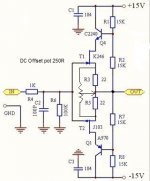
I wanted to give some 'pay back' for all the work you've done in the thread! Since you're not into Tina, feel free to request any sim.
...
Jeff if it's not too much trouble can you see how this SIM's up, also I'm very interested to see what the input (with & without the 100k) and output impedances are.
I may try this straight from the TZ of the AD844 next weekend
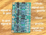
This is one of the ebay buffers from raindrophuey cost me $10 shipped all ready made up.
Cheers George
Attachments
No problem!
One way to quickly DC analyze a circuit is to see gain devices as high input impedance and low output impedance.
So input impedance (w 100k) would be 100k in parallel with 2 inputs in parallel
So 100k || 1M || 1M so like 90k
no 100k: 1M||1M = 500k
Output impedance 22||22 =10ohm
I'll sim it at lunch!
Cheers,
Jeff
PS My same buffers had significant DC offset (+50, +80mV) indicating that the input FETs aren't matched! And the seller didn't care ...
Last edited:
Nice case ! But also from aluminum....and anodized it seems.
Actually, it is alodine, which remains electrically conductive while preventing the aluminum from corroding.
From their website:
"Series 14 rack-mount chassis have been carefully engineered and improved to provide both reliable EMI/RFI shielding and structural rigidity. Special treatment has been used for all panel contact areas to guarantee the shielding. Test data from our chassis reached 70dB electrical noise attenuation for varying frequencies. Our EMI/RFI shielded chassis are specially designed by our electrical engineering team with expertise in RFI shielding and testing. Par-Metal can custom manufacture, modify, and test the EMI/RFI shielded enclosures to meet your specifications. We can also save you time and money by delivering your custom order in lead times of 1 to 3 weeks."
and:
"Add suffix-x for your choice of color or finish:
-A alodine (EMI / RFI shielded)
-B black anodize (no EMI / RFI shielding)
-C clear anodize (no EMI / RFI shielding)
-E painted beige (mask for EMI / RFI shielding)
-G painted gray (mask for EMI / RFI shielding)
-N clear alodine (EMI / RFI shielding)
-P painted black (mask for EMI / RFI shielding)
-S black anodize front and gold alodine body"
And thanks, it is a very well made chassis.
It seems that using a steel chassis can cause problems for circuit boards that are too close to it, meaning that the box has to be bigger for a given board size.
What's 'normal' depends on context. Normal filtering on cables in the audio world is none, whereas normal in the RF world is feedthrough capacitors and fully enclosed (i.e. faraday shielded) boxes with gaskets on the lids.
Yep - and the ones you showed are scarcely any better due to absence of cable filtering.
I don't agree that "cable filtering", by which I assume you mean filtering the signal at the cable connector on the chassis, is a serious weakness nor a serious problem for well designed cables. I use Canare Star Quad cable, which is designed to dramatically reduce RF interference. See the attached document for reference.
Attachments
That's a big cap to ground that the PCM1704 will see, I'm too scared to try that, it could cook the 1704.
Cheers George
Below the -3dB point, the capacitor looks like an open circuit to the DAC. Above the -3dB point, it more and more looks like a short circuit. So, since the vast majority of the spectral energy coming out of the DAC is in the audio range, which is below the -3dB point, then only a small amount of high frequency "junk" becomes a short circuit for the DAC. I don't think that it will be a problem, but have not tested it in real life yet so I am not completely certain.
- Home
- Source & Line
- Digital Line Level
- Using the AD844 as an I/V