I don't think you'd "hear" the difference of that filter--it's effect at audio freq would be minimal.
What it's probably doing is changing the loading of the AD844 or the increase in high freq is affecting something down chain. Something strange and technical no doubt! I'll sim it up for ya later tonight!
Gotta go play with me' boy!
Cheers,
Jeff
PS Filters are weirdass, what freq is your 3rd order at? It could be interacting with that 100k ...
Last edited:
Thanks Jeff, but I have my doubts whether siming it will show anything, as I think it's a stability issue only under musical dynamic conditions. As it looks perfectly stable on the crow with all test waves either way. I believe the 570pf is sending it into slight ringing, as audibly it 's giving the opposite to what you would expect, sweeter without the cap. And I forgot to mention with the 560pf capthe DC offset absolutly stable to within .5mV Without the cap it can wander just a touch more, still very good.
Cheers George
Cheers George
PCM1704: current output DAC, dual mono, single ended, 1.2 mA full scale current, 0V reference voltage. I'm not sure how much current offset it has but I left it as 2mA and cancelled it with the external current source (IS1 2mA).

2.7k with 560pf and 1pf

Actually I take it back, maybe this would affect high freqs ...
2.7k with 560pf and 1pf
Actually I take it back, maybe this would affect high freqs ...

PCM1704: current output DAC, dual mono, single ended, 1.2 mA full scale current, 0V reference voltage. I'm not sure how much current offset it has but I left it as 2mA and cancelled it with the external current source (IS1 2mA).
2.7k with 560pf and 1pf
View attachment 331768
Actually I take it back, maybe this would affect high freqs ...
Thanks Jeff.
I take it
The brown in both graphs is 2.7k no cap
The red in the top graph is 2.7k with 1pf
The green in the lower graph is 2.7k with 560pf
I also noted that your taking the output from pin 6 and not pin 5?
Cheers George
Hey George,
I wanted to give some 'pay back' for all the work you've done in the thread! Since you're not into Tina, feel free to request any sim.
Speaking of sim, all I wanted to show was the basic freq changes. I'm a bit leery of trying to connect even something that seems so basic as higher roll off = more highs
If this was basic filters maybe .... but this is a wacked out IV
Again, I don't understand enough about the common base configuration to know if the cap is required ...
What we do know is at least what the sim is telling us:
A lot more hi freq gets to the next stage with no cap ...
And there is some change to audio freq (I'll zoom in for you)

Seems minimal but you should know whats going on ...
I wanted to give some 'pay back' for all the work you've done in the thread! Since you're not into Tina, feel free to request any sim.
Speaking of sim, all I wanted to show was the basic freq changes. I'm a bit leery of trying to connect even something that seems so basic as higher roll off = more highs
If this was basic filters maybe .... but this is a wacked out IV
Again, I don't understand enough about the common base configuration to know if the cap is required ...
What we do know is at least what the sim is telling us:
A lot more hi freq gets to the next stage with no cap ...
And there is some change to audio freq (I'll zoom in for you)
Seems minimal but you should know whats going on ...
Last edited:


Thanks for all this work Jeff, judging by all these sim's it's good with or without the cap, up to the individual what he like the sound of.
But I can't believe I'm hearing a few degrees of phase shift from 5khz to 20khz. It's one of those mysteries of audio where a 1st order HF roll off filter at 100khz sounds for some reason a tad brighter than no filter?
Cheers George
But I can't believe I'm hearing a few degrees of phase shift from 5khz to 20khz. It's one of those mysteries of audio where a 1st order HF roll off filter at 100khz sounds for some reason a tad brighter than no filter?
Cheers George
You might be hearing reduced 'grunge' caused by better bandlimiting as 'brighter' as its probably making b*gger all difference in the audio band. But lopping off the HF will reduce the overall IMD and give a clearer, more dynamic sound. This is how I'm hearing the difference in tweeter output in my chipamps - the bad ones sound 'dull' which has nothing to do with the FR, rather the IMD from RF in the signal and on the PSU rails.
Abraxalito's got the technical explanation of what I was trying to say.
If you're hearing something, it probably isn't the direct and very small change in the frequency response. Rather it's the high frequency being mixed down into the audio band--that's IMD!
If you remember how radios work (audio on a high freq carrier freq) its the same concept: two frequencies (f1 audio and f2 carrier) mixing in a controlled and linear fashion and producing multiple copies at different frequencies (f1-f2 and f1+f2). You create a 3rd signal (f1+f2) that's your high freq carrier and your audio signal mixed together--it's high freq (good for transmitting with a small antenna) and has your info in it.
Send.
Receive.
Reverse the process in the same controlled and linear fashion to separate the signals (f1-f2) and get your audio f1. ... Wow, that takes me back to the labs of first year ... Ah, what was I sayin .... oh ya ...
When the mixing is done poorly or unintentionally it's often non-linear and now you also get small copies at 2x (f1-f2) and 2x (f1+f2), and 3x (f1-f2) and 3x (f1+f2), 4x ..., 5x ....
What this means for us is that you get copies of high freq Mhz stuff all over the place and some can mix down quite far when (f1-f2) is large and the multiplier is large (20x) and the copies are ... loud. What this subjectively sounds like is more difficult ...
Here are a few danger freqs of interest:

http://www.diyaudio.com/forums/anal...-phono-preamp-open-project-5.html#post3357184
If you're hearing something, it probably isn't the direct and very small change in the frequency response. Rather it's the high frequency being mixed down into the audio band--that's IMD!
If you remember how radios work (audio on a high freq carrier freq) its the same concept: two frequencies (f1 audio and f2 carrier) mixing in a controlled and linear fashion and producing multiple copies at different frequencies (f1-f2 and f1+f2). You create a 3rd signal (f1+f2) that's your high freq carrier and your audio signal mixed together--it's high freq (good for transmitting with a small antenna) and has your info in it.
Send.
Receive.
Reverse the process in the same controlled and linear fashion to separate the signals (f1-f2) and get your audio f1. ... Wow, that takes me back to the labs of first year ... Ah, what was I sayin .... oh ya ...
When the mixing is done poorly or unintentionally it's often non-linear and now you also get small copies at 2x (f1-f2) and 2x (f1+f2), and 3x (f1-f2) and 3x (f1+f2), 4x ..., 5x ....
What this means for us is that you get copies of high freq Mhz stuff all over the place and some can mix down quite far when (f1-f2) is large and the multiplier is large (20x) and the copies are ... loud. What this subjectively sounds like is more difficult ...
Here are a few danger freqs of interest:
http://www.diyaudio.com/forums/anal...-phono-preamp-open-project-5.html#post3357184
Last edited:
So you can see why RF and EMI is so nasty and PMA keeps harping on about it.
Which brings me to the difference between your 1704 circuit and the 1541 circuit.
It has a sort of input filter cap (only):

Which shaves off some RF and lots of EMI before it even gets to the 844 let alone your 3rd order filter!

We'd have to figure out a good value for your circuit.
Which brings me to the difference between your 1704 circuit and the 1541 circuit.
It has a sort of input filter cap (only):
Which shaves off some RF and lots of EMI before it even gets to the 844 let alone your 3rd order filter!
We'd have to figure out a good value for your circuit.
So you can see why RF and EMI is so nasty and PMA keeps harping on about it.
PMA isn't the only one - its my major hobby-horse too
Thanks for putting all the mathematical meat on the bones of my writing.Here's why your 3rd order filter may have trouble with RF/EMI:

... and things get even stranger because you've probably got multiple feedbacks going back to both the pos and neg inputs ...
c o m p l e x
Remember the previous chart, sources at .4, .9, 1.8, 2.4, 3.6 and 5GHz

... and things get even stranger because you've probably got multiple feedbacks going back to both the pos and neg inputs ...
c o m p l e x
Remember the previous chart, sources at .4, .9, 1.8, 2.4, 3.6 and 5GHz
So what sort of opamp (fet or bi-polar, fast slow, best settling time ect) would be the better 3rd order L/P opamp to use, at the moment I am using an AD825 which gives to my ear the better sound out of the hundreds I have so far tried.
My FR is is only about .1db down at 19.99k using 560 cap and 3rd order L/P, noise on the output is virtualy nil, 1khz square wave looks perfectly square with the tinyest bit of ringing on the leading and trailing edge (gib phenonmen)
Cheers George
My FR is is only about .1db down at 19.99k using 560 cap and 3rd order L/P, noise on the output is virtualy nil, 1khz square wave looks perfectly square with the tinyest bit of ringing on the leading and trailing edge (gib phenonmen)
Cheers George
Last edited:
AD825 is by all accounts a good one - its rated by JC for SQ and Walt Jung found it didn't give RF related problems in his regulator (whereas AD797 did).
As a suggestion you could try one of the Barrie Gilbert style 'active feedback amplifiers'. That would be AD830, AD8129 and AD8130. Be warned though they're not particularly low noise - the AD8129 is the lowest but needs a gain of 20dB at least. In my experience the AD830 (the only one I've tried so far) is very RF-immune in that it doesn't give nasty sibilance when hung off the output of my TDA1387 DAC with only 1kohm and 1nF protecting it from hundreds of mV of RF.
As a suggestion you could try one of the Barrie Gilbert style 'active feedback amplifiers'. That would be AD830, AD8129 and AD8130. Be warned though they're not particularly low noise - the AD8129 is the lowest but needs a gain of 20dB at least. In my experience the AD830 (the only one I've tried so far) is very RF-immune in that it doesn't give nasty sibilance when hung off the output of my TDA1387 DAC with only 1kohm and 1nF protecting it from hundreds of mV of RF.
Last edited:
Sorry, Dude, I shouldn't have been so dramatic!
Didn't mean to imply there is anything wrong with your circuit. Fact is, most circuitry has to deal with this and does to a varying degree.
I was just trying to illustrate what abraxalito was talking about and why there could be issues with RF/EMI and how it actually affects the audio band. ... and why there may be solid technical reasons for the 560p cap and its rolloff.
Neat thing here is how it connects back to that radio mixing idea. RF/EMI is a fact of life (in general) and especially so with the 'staircases' in current DAC I/V, so you can either try to filter it out of your circuits and/or build circuits that can handle it.
That is, handle it linearly and just pass it through without mixing it all up with the audio.
"Mixing it all up": literally and technically: non-linear mixing producing 2x, 3x, 4x, 5x, (f1+f2) and (f1-f2)...
That's why high speed parts make sense:
AD825: High speed, 41 MHz,−3dB bandwidth, 125 V/μs slew rate, 80 ns settling time
But high speed parts need to be laid out and bypassed properly ...
Enter abraxalito on hobby horse:
Last edited:
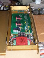
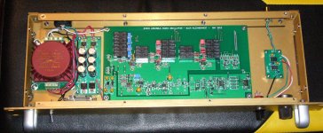
Yet another reason to put your gear inside of RFI resistant metal boxes. Most of those "pretty" boxes they sell to hobbyists do not shield RF because they are anodized aluminum. Here's what a more professional RFI resistant box looks like. This is from Par-Metal (I am only a satisfied customer) and contains a SV oscillator (not quite finished yet).
Par-Metal
Par-Metal
Attachments
- Home
- Source & Line
- Digital Line Level
- Using the AD844 as an I/V