Zoran said:Hi Erik
Could You please
take a close photo from Your output board from Wadia ?
I am curios how they did that and maybe others too...

Double layered...
")
I guess the only way to go is to put a request out for eg. a Wadia outputboard ...owners with a separate clock might be using also a separate RCA so they can sell the board....I know that Wadia was charging 1500 dollars for a certain modification including such a board...(with ATT)
Another clone rears it's ugly drive!
First, I want to say thanks to Peter and everyone else who contributed ideas, suggestions, inspiration, and details on this thread. We stand on the shoulders of giants!
I got my clone running yesterday. It's a bit rough and ready... still using the door-closing switch (just bent it closed and open it with my fingers when I load a CD as someone suggested), the transformer needs a cover, and I need to get some real AC wiring setup for it. Eventually I may also do some sort of cover over the PS and possibly the transport mechanism.
But it runs...
AND HOW IT RUNS! WOW! Now I know what all the fuss was about. The sound is very 'dense' and very heavily 'textured', where the buzzes, rattles, tinks, and all the other subtle noises of an instrument or voice come out and add a stronger sense of realism. And it still does a good job of keeping all the musical elements separately audible while presenting a good coherent 'whole' musical experience. It pulled me into the musical experience in a way my current rig (a professionally modified Oppo 970... which is no slouch!) doesn't even dream of.
And it's not even broken in yet!
Ok, now for some questions for Peter...
1. In your latest creation, did you find it necessary to remove the chip bypass caps on the bottom of the board towards the center?
2. Also Peter, did you find much difference between having the digital out Rs at the board vs the jack? I've got them at the jack and initially set it up with the 75R/75R from your original build (I'd ordered them back in the spring), but I'll be trying the 300R/100R to see if it sounds better with my setup.
3. Have you tried the delrin clamp with the new setup? If so, how'd it sound?
It's funny to be finishing this now... also thanks to Peter, I starting down the path of setting up an audiophile computer music drive based on cics's AOB and cMP work... and watching closely what Peter does with his version of the same. With some work, this may be my last CDP.
Again, thanks everyone!
Greg in Mississippi
Attachments

Re: Another clone rears it's ugly drive!
Hi Greg,
I only removed 2 ceramic bypasses, the ones that were with 220uF and 470uF caps (and choke). I didn't touch anything else as it sounded good to me as it was.
I noticed slight improvement after I cut off RCA jack on my cable and soldered wires directly to a board: more immediacy in a sound.
I didn't try that clamp on my recent transport as I have only one clamp and taking it off is a major problem. Custom clamp is fine, but not really neccessary: the result is rather subtle.
Good luck with a computer, I'm working on mine too
Greg Stewart said:Ok, now for some questions for Peter...
1. In your latest creation, did you find it necessary to remove the chip bypass caps on the bottom of the board towards the center?
2. Also Peter, did you find much difference between having the digital out Rs at the board vs the jack? I've got them at the jack and initially set it up with the 75R/75R from your original build (I'd ordered them back in the spring), but I'll be trying the 300R/100R to see if it sounds better with my setup.
3. Have you tried the delrin clamp with the new setup? If so, how'd it sound?
Hi Greg,
I only removed 2 ceramic bypasses, the ones that were with 220uF and 470uF caps (and choke). I didn't touch anything else as it sounded good to me as it was.
I noticed slight improvement after I cut off RCA jack on my cable and soldered wires directly to a board: more immediacy in a sound.
I didn't try that clamp on my recent transport as I have only one clamp and taking it off is a major problem. Custom clamp is fine, but not really neccessary: the result is rather subtle.
Good luck with a computer, I'm working on mine too
Re: Re: Another clone rears it's ugly drive!
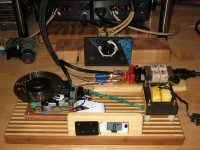
Gotta love direct-wiring. You likely cannot see in my poor photo, but the SPDIF cable is hard-wired into your NOS DAC's input... along with the cables into and out of my jury-rigged ladder volume control AND the speaker cables to the speakers.
I hardwire as much as I can... cheap improvements (actually cost-effective as I save on expensive connectors!).
One aspect of the sound through the Shigaclone and NOS DAC that I neglected to mention yesterday is something that will make sense to vinyl junkies here, especially ones who were around in the late '70s/early '80s... a 'Direct Disk' sense to the sound, in that there is an improved sense of immediacy and intimacy with the sound, just like a direct disk record is to a regular studio-produced record.
I've got most of the gear here now after a frenzy of mail-orders last weekend and early last week. I get the harddrives in mid-week and can start loading it up then! I'm doing a standard AOB/cMP-Squared setup to start, knowing that there are some improvements to be had with casing and power supplies, but it appears to be a complex enough job that just getting it running stock will be a sufficient challenge to start.
Again, thanks!
Greg in Mississippi
P.S. I am very curious to hear what will change when I go to the 300R/100R digi-out R's. I wonder if my digi cable is short enough to do it without the R's (9" total, 3" drive board to jack, 6" plug to DAC board).
Peter Daniel said:Hi Greg,
<SNIP>
I noticed slight improvement after I cut off RCA jack on my cable and soldered wires directly to a board: more immediacy in a sound.
<SNIP>
Gotta love direct-wiring. You likely cannot see in my poor photo, but the SPDIF cable is hard-wired into your NOS DAC's input... along with the cables into and out of my jury-rigged ladder volume control AND the speaker cables to the speakers.
I hardwire as much as I can... cheap improvements (actually cost-effective as I save on expensive connectors!).
One aspect of the sound through the Shigaclone and NOS DAC that I neglected to mention yesterday is something that will make sense to vinyl junkies here, especially ones who were around in the late '70s/early '80s... a 'Direct Disk' sense to the sound, in that there is an improved sense of immediacy and intimacy with the sound, just like a direct disk record is to a regular studio-produced record.
Good luck with a computer, I'm working on mine too
I've got most of the gear here now after a frenzy of mail-orders last weekend and early last week. I get the harddrives in mid-week and can start loading it up then! I'm doing a standard AOB/cMP-Squared setup to start, knowing that there are some improvements to be had with casing and power supplies, but it appears to be a complex enough job that just getting it running stock will be a sufficient challenge to start.
Again, thanks!
Greg in Mississippi
P.S. I am very curious to hear what will change when I go to the 300R/100R digi-out R's. I wonder if my digi cable is short enough to do it without the R's (9" total, 3" drive board to jack, 6" plug to DAC board).
I only removed 2 ceramic bypasses, the ones that were with 220uF and 470uF caps (and choke). I didn't touch anything else as it sounded good to me as it was.
Hi Peter,
which caps are these ? and where are they located?
Thanks
Those would be E5 and R5 in this pdf: http://tim.cheapo.cc/images/CD player mods.pdf
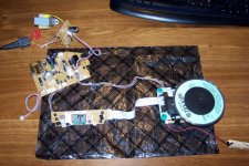
About three quarters of an hour of work and I had the innards of the '51 lying in front of me playing a CD! The same amount of time more and I had soldered the resistors and cable on the Dout/GND and was ready to play. First a quick check of the S/PDIF-level with the scope: loaded with an S/PDIF input: nearly 550 mVpp, well within spec.
Before starting serious listening I fumbled with the magnet in the puck until I was satisfied it was centered.
Some of the best recordings in my collection are on the test CD "My Disc" by Sheffield labs. I especially like the clarity and dynamics on certain tracks. For now my verdict is "not bad", but it's not burned in yet (nor has the DAC) and I haven't even begun the modification process. Next step: mount it on a board.
Attachments
Re: Re: Re: Another clone rears it's ugly drive!
No, it's not short enough and never will be simply because the cable is not correctly terminated into its characteristic impedance at the sending end. The 300/100 termination matches the digital output of the DSP chip to the characteristic impedance of your cable which hopefully is 75 ohms or thereabouts. Properly matched terminations result in fewer reflections and hence better signal integrity and depending on timing, somewhat less resulting jitter in the output of the comparator/slicer used in the receiver IC. There is another consideration as well and that is the voltage level at the input to your dac's receiver IC, the spdif standard with proper terminations will result in an input receiver level in the 500mVpp range and the dynamic range of most receivers not intended to support AES-EBU levels is smaller than the ~4Vpp you are currently hitting it with. In some cases spdif receiver ICs will not lock on a signal that is so far out of bounds, and in others performance is significantly degraded as levels are high enough to start to forward bias protection clamp diodes in the substrate of the receiver IC or degrade the performance of the receiver input circuitry.. (I think I have already mentioned these issues a few times in this thread.)
FWIW I think the Shigaclone is great, and in my system it offers the most natural sounding CD playback I have yet experienced, that said it REALLY pales in comparison to good analog (R2R tape or LP) or SACD. I have also downloaded live pcm recordings of admittedly pretty obscure bands from www.archive.org with 24 bit 48K or 96K sample rates and these easily better my best CDs for sound quality in many instances as well. (Media server required, and files are flac format.) Might as well get the best from your CD collection possible, but don't fall into the trap of thinking that CD offers anything close to the best achievable audio performance - it clearly doesn't and can't.
Greg Stewart said:
<snip>
P.S. I am very curious to hear what will change when I go to the 300R/100R digi-out R's. I wonder if my digi cable is short enough to do it without the R's (9" total, 3" drive board to jack, 6" plug to DAC board).
No, it's not short enough and never will be simply because the cable is not correctly terminated into its characteristic impedance at the sending end. The 300/100 termination matches the digital output of the DSP chip to the characteristic impedance of your cable which hopefully is 75 ohms or thereabouts. Properly matched terminations result in fewer reflections and hence better signal integrity and depending on timing, somewhat less resulting jitter in the output of the comparator/slicer used in the receiver IC. There is another consideration as well and that is the voltage level at the input to your dac's receiver IC, the spdif standard with proper terminations will result in an input receiver level in the 500mVpp range and the dynamic range of most receivers not intended to support AES-EBU levels is smaller than the ~4Vpp you are currently hitting it with. In some cases spdif receiver ICs will not lock on a signal that is so far out of bounds, and in others performance is significantly degraded as levels are high enough to start to forward bias protection clamp diodes in the substrate of the receiver IC or degrade the performance of the receiver input circuitry.. (I think I have already mentioned these issues a few times in this thread.)
FWIW I think the Shigaclone is great, and in my system it offers the most natural sounding CD playback I have yet experienced, that said it REALLY pales in comparison to good analog (R2R tape or LP) or SACD. I have also downloaded live pcm recordings of admittedly pretty obscure bands from www.archive.org with 24 bit 48K or 96K sample rates and these easily better my best CDs for sound quality in many instances as well. (Media server required, and files are flac format.) Might as well get the best from your CD collection possible, but don't fall into the trap of thinking that CD offers anything close to the best achievable audio performance - it clearly doesn't and can't.
Re: Re: Re: Re: Another clone rears it's ugly drive!
How is your Shigacl. about? The "simply one" (last one tried by Peter) or... what else?
Thanks.
kevinkr said:
FWIW I think the Shigaclone is great, and in my system it offers the most natural sounding CD playback I have yet experienced, that said it REALLY pales in comparison to good analog (R2R tape or LP) or SACD.
How is your Shigacl. about? The "simply one" (last one tried by Peter) or... what else?
Thanks.
Re: Re: Re: Re: Re: Another clone rears it's ugly drive!
My Shigaraki is almost a year old now, and is modeled on the original design Peter came up with.. I used all Black Gate capacitors and a very big overkill psu with LM7808 just for the mechanism. Uses most of the rest of the ideas where applicable - what is different is that it is based on the RC-EZ32 and shares more features in common with the actual Shigaraki than most clones. (Micro-controller is on a separate board and the display is slightly different- displays track and time, although not simultaneously.) The mechanism is supported by two heavy aluminum stand-offs on an aluminum plate that is mass loaded with 3.5kg of bronze, overall mine weighs in at about 6kg. The mounting technique was very audible as Peter said and the additional mass helped as well. There are some pictures of it in this thread, it is far from the prettiest of the lot as I have very limited metal working resources and skills. (Electrically it is very good.)
The quality of the spdif signal looks very good, good open eye pattern, no ground bounce or noise present. I've not really seen better, and I have seen much worse. I have no way to measure spdif jitter or link vswr unfortunately. (I did work very hard at making everything a real 75 ohms from connectors, internal cabling, external cables, to termination techniques.)
It sounds really good, but I have better sounding sources yet which is what I was hinting at, these are not however CD based. I think it would be hard to do a lot better without expending obscene amounts of money. I expect Eric's version to better mine in significant ways due to superb quality of execution and the additional effort he has put into optimizing things like power supplies, shielding, and mechanical issues I barely touched by comparison. (I'll bet he has spent at least 10X what I spent on mine when you factor in time and materials. )
I do think it was money well spent and at some point I would like to build another, perhaps one based on one of the Sanyo boom boxes recently mentioned.
Kooka said:
How is your Shigacl. about? The "simply one" (last one tried by Peter) or... what else?
Thanks.
My Shigaraki is almost a year old now, and is modeled on the original design Peter came up with.. I used all Black Gate capacitors and a very big overkill psu with LM7808 just for the mechanism. Uses most of the rest of the ideas where applicable - what is different is that it is based on the RC-EZ32 and shares more features in common with the actual Shigaraki than most clones. (Micro-controller is on a separate board and the display is slightly different- displays track and time, although not simultaneously.) The mechanism is supported by two heavy aluminum stand-offs on an aluminum plate that is mass loaded with 3.5kg of bronze, overall mine weighs in at about 6kg. The mounting technique was very audible as Peter said and the additional mass helped as well. There are some pictures of it in this thread, it is far from the prettiest of the lot as I have very limited metal working resources and skills. (Electrically it is very good.)
The quality of the spdif signal looks very good, good open eye pattern, no ground bounce or noise present. I've not really seen better, and I have seen much worse. I have no way to measure spdif jitter or link vswr unfortunately. (I did work very hard at making everything a real 75 ohms from connectors, internal cabling, external cables, to termination techniques.)
It sounds really good, but I have better sounding sources yet which is what I was hinting at, these are not however CD based. I think it would be hard to do a lot better without expending obscene amounts of money. I expect Eric's version to better mine in significant ways due to superb quality of execution and the additional effort he has put into optimizing things like power supplies, shielding, and mechanical issues I barely touched by comparison. (I'll bet he has spent at least 10X what I spent on mine when you factor in time and materials. )
I do think it was money well spent and at some point I would like to build another, perhaps one based on one of the Sanyo boom boxes recently mentioned.
Re: Re: Re: Re: Re: Re: Another clone rears it's ugly drive!
Interesting post, thanks!
kevinkr said:
My Shigaraki is almost a year old now, and is modeled on the original design Peter came up with.. I used all Black Gate capacitors and a very big overkill psu with LM7808 just for the mechanism. Uses most of the rest of the ideas where applicable - what is different is that it is based on the RC-EZ32 and shares more features in common with the actual Shigaraki than most clones. (Micro-controller is on a separate board and the display is slightly different- displays track and time, although not simultaneously.) The mechanism is supported by two heavy aluminum stand-offs on an aluminum plate that is mass loaded with 3.5kg of bronze, overall mine weighs in at about 6kg. The mounting technique was very audible as Peter said and the additional mass helped as well. There are some pictures of it in this thread, it is far from the prettiest of the lot as I have very limited metal working resources and skills. (Electrically it is very good.)
The quality of the spdif signal looks very good, good open eye pattern, no ground bounce or noise present. I've not really seen better, and I have seen much worse. I have no way to measure spdif jitter or link vswr unfortunately. (I did work very hard at making everything a real 75 ohms from connectors, internal cabling, external cables, to termination techniques.)
It sounds really good, but I have better sounding sources yet which is what I was hinting at, these are not however CD based. I think it would be hard to do a lot better without expending obscene amounts of money. I expect Eric's version to better mine in significant ways due to superb quality of execution and the additional effort he has put into optimizing things like power supplies, shielding, and mechanical issues I barely touched by comparison. (I'll bet he has spent at least 10X what I spent on mine when you factor in time and materials. )
I do think it was money well spent and at some point I would like to build another, perhaps one based on one of the Sanyo boom boxes recently mentioned.
Interesting post, thanks!
I have removed all suggested parts and as stated before I am using the Sanyo boombox ( with a Monica 2 DAC)
I tried 390/91R originally and it sounded OK (was a bit disappointed)
I tried 75/75R and that sounded great.
Then lastly I tried 200/75 and that sounded pretty great also
When I get a chance I will try 291/100 as I have read that is close to SPDIF spec.
Still on the stock power supply though and based on pine board!
Kooka said:Just disassembled my boombox, and from its own psu I test (no load) 13vdc (on dc+ dc- pins), is it normal..? Can I feed the board with those values?
Like you said: no load. In no load condition higher than nominal voltage is normal (esp. in unregulated PSU like this). If I measure the voltage on the smoothing cap on the rectify board board (unloaded) I measure 14.9 V. When connected to the main board this drops to around 12 V.
jitter said:
Like you said: no load. In no load condition higher than nominal voltage is normal (esp. in unregulated PSU like this). If I measure the voltage on the smoothing cap on the rectify board board (unloaded) I measure 14.9 V. When connected to the main board this drops to around 12 V.
I know about the drop when loaded, but from 8V to more than 13V there's a lt of room...
Kooka said:
I know about the drop when loaded, but from 8V to more than 13V there's a lt of room...
What voltage are you talking about (I don't see DC+ and DC- markings on my pcbs, I have the '51)?
The mainboard gets 12 V from the rectify board. The mainboard makes 8 V out of the 12 V and feeds it to the CD-board (and also to other now unconnected boards).
Edit: the 8V output from the mainboard measures 8.6 V unloaded and 8.4 V loaded in my case.
- Home
- Source & Line
- Digital Source
- Finally, an affordable CD Transport: the Shigaclone story