After reading up on the Cirrus voltage out type DACs I realised I should add a low pass filter, if for no other reason than to protect my amplifiers if they don't have effective filtration of their inputs and my DAC might pass them harmful high frequencies.
Will a simple passive filter (a resister and a capacitor) do the job or is it better to use an opamp and make an active filter?
What should the cut off frequency be? I know human hearing tops out at 20khz, but should the LP filter start at that frequency or a bit higher?
For a passive filter, is the cut off frequency determined solely by the values of the resistor and capacitor? If so, how do I calculate those values for a given frequency?
Yes, but I didn't really understand it, hence my questions. The data sheet says:
The schematic, which I really don't understand, what's the tube-like thing labelled audio output, and what is R ext, for instance:

The analog filter present in the CS4344 family is a switched-capacitor filter followed by a continuous time low pass filter.
The schematic, which I really don't understand, what's the tube-like thing labelled audio output, and what is R ext, for instance:
Attachments
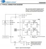
It represents a shielded coaxial type cable. The black arrow pointing into it would then presumably be the output jack on the dac box.
Rext would be the input impedance of your power amp or other external load, where 'ext' stands for external. Typically that might be something like 2k-30k ohms for consumer equipment.
If you want an exact value and don't know what you might use for a load you could always add an opamp buffer and make Rext the input impedance of that buffer circuit. The opamp buffer could then have maybe a 220 ohm output series resistor for stability and current limiting. That way Rext could be a well defined part of the dac output filter. Somewhere around there might also be a good place to add a volume control.
Or, you could just make a rough guess, pick a number for Rext, and proceed as if it were accurate.
Or, another possibility might be there is already the exact filter you need on the circuit board and so far you are just trying to take an output signal before the filter. In that case, you could simply move the point where you are tapping off an output signal so it is after the presumed preexisting filter rather than before it.
Thanks Mark, your explanation cleared it all up for me. I thought that was a cable and an external value, but I really didn't want to start making guesses and preferred to ask - you see now why I've put the ESS board to one side for a while as I clearly need to move my knowledge and skills forward a good deal before I'm ready and able to take on a more complex job.
I already have a buffer board that uses discrete components, so I could use that, I read that the output of the CS DAC chip is too high for most equipment, so the buffer is needed to fix that issue.
I also have some opamps - a MUSES8920 and an LME49720, plus some 8-pin sockets and matrix boards so I could build an opamp buffer instead, probably I'll try the discrete board first and if there are any issues, I'll roll my own opamp buffer, seeing as I have the parts in hand.
How would I determine the input impedance of the buffer?
For the 10k and 470 ohm resistors, would ceramic wire wound types be okay? I already have a load of them but I remember you saying to use metal film types in the output stage for the ESS board as they are best for low distortion.
God, so many questions, good job I enjoy learning!")
I already have a buffer board that uses discrete components, so I could use that, I read that the output of the CS DAC chip is too high for most equipment, so the buffer is needed to fix that issue.
I also have some opamps - a MUSES8920 and an LME49720, plus some 8-pin sockets and matrix boards so I could build an opamp buffer instead, probably I'll try the discrete board first and if there are any issues, I'll roll my own opamp buffer, seeing as I have the parts in hand.
How would I determine the input impedance of the buffer?
For the 10k and 470 ohm resistors, would ceramic wire wound types be okay? I already have a load of them but I remember you saying to use metal film types in the output stage for the ESS board as they are best for low distortion.
God, so many questions, good job I enjoy learning!
Wire wound resistors are good for some things, but they are typically rather inductive. So think about what the circuit would do if you added an inductor in series with any wire wound resistor. The inductance will increase the impedance as frequency goes up.
The 10k resistor looks like it mostly provides a ground reference for the caps when the external load has a DC blocking cap on the input.
The 470 ohm resistor works with the cap 'C' to make a low-pass filter. The exact corner frequency of that RC filter is also affected by Rext. If the 470 ohm were inductive it would change the filter frequency response. To figure out how much you would need to know the amount of inductance. You could then model the equivalent circuit including inductance using something like LTSpice, or make a calculation.
The 3.3uf electrolytic appears to be mostly a DC blocking cap.
For lowest distortion thin film and metal film resistors are the best. Thin film are available in very tight tolerances for when good matching is needed (like for a dac differential amplifier) and are probably best for very lowest distortion. While this dac probably does not need the best, an ES9038Q2M dac should use well matched thin film for the output stage, IMHO.
Depending on how much you know now or have studied before and forgotten, you might start in different places now. You will have to say a little more about that for us to get idea of where you are at if you would like recommendations. Not just for electronics, but for math and science too. Those things are all very much related.
I have no education in maths or science beyond my school days, I'm a photographer turned journalist by trade so I need to learn from a highschool level.
I already fitted a pair of 100uf Rubycon electrolytics in the position those 3.3uF caps are in the schematic, I just chose the Rubycons because I had them and my understanding was that any value from 1uF and up is fine for DC blocking; however, I can always remove them and replace them with different caps.
It sounds to me like it would be simplest and best to just buy some suitable resistors, will any thin film type of the right value be okay?
I suggest you exactly follow the datasheet for that Cirrus DAC just like I did for this one:
http://www.diyaudio.com/forums/digi...80h-direct-output-cs4361-dac.html#post5253111
Mine is the exact same, so you should use C= 1000pF.
...my understanding was that any value from 1uF and up is fine for DC blocking...
Where did you get that idea from? In reality, it depends. A capacitor has a frequency dependent impedance. The impedance is greater at lower frequencies. Whether or not 1uf is big enough depends on what other impedances are in the circuit. It could be much too small in some cases, in which event you would notice a lack of deep bass or maybe no bass at all.
For home study without Calculus, a very popular introductory book:
Practical Electronics for Inventors, Fourth Edition
Then, an extremely popular electronics book and reference without heavy theory, but that assumes a fair amount preexisting electronics knowledge is:
The Art of Electronics, by Horowitz and Hill. Now in the 3rd edition. Expensive, well but worth it. Maybe some older editions on the net for accompanying college courses, don't know.
-----------------------------------------
For math and science lessons and electronics with more powerful-level theory there are various resources. Some people seem to like Kahn Academy to get started which is not perfect, but can introduce subjects starting from elementary school and continuing maybe up through the first two years of College, or at least Junior College:
Khan Academy | Free Online Courses, Lessons & Practice
One thing that is quite true for virtually everyone: learning math requires doing the homework problems. No way around some real studying if one is serious.
Then, for a pretty good, well-rounded text book on introductory electronics (that assumes some preexisting knowledge equivalent to a couple of years of college)
Electronics - Fundamentals and Applications
by D Chattopadhyay and P C Rakshit
Now in at least the 13th edition, maybe later.
Yeah, one thing I've learned already is that a lot of people who dabble in diy audio don't have a solid background in electronics and instead learn just enough to be dangerous. It's why I ask so many questions - I'm conscious I don't know enough to not be mislead and thus make mistakes based on things I read on the internet.
I've made a circuit on a piece of stripboard with two strings of five 2200uF caps in parallel, to use for DC smoothing between the regulator and the DAC board.
I read that you need to add a smaller value cap in parallel to the last cap in order to not lose high frequencies.
But despite reading lots I can't find the answer to how to calculate the correct value for this smaller cap.
So can someone guide me in what value to use for this small cap in order to preserve high frequencies?
Depending on various factors of construction, caps have practical frequency ranges over which they work like reasonably close to the theoretical model of a capacitor. No cap is close to an ideal cap from DC to light. If one needs a wider frequency range than one type of cap is able to serve well, then a solution might be to use various types of caps to to widen effective frequency range. That's all. For standard electrolytic caps, they can start looking more like inductors by up around 100kHz in some cases. There may be graphs of impedance vs frequency that show the effects. When one cap reaches its practical limit, maybe another type of cap in parallel would be the fix. It depends on the actual caps one has and the frequency range one needs.
These are blue Phillips 2200uF 16v electrolytics, they also have 037QS and C7 printed on them.
The frequency range would be upto 20khz, although I doubt I can hear much if anything over 16kHz.
I suppose either an MKP polyester type or a tantalum type would do the trick, just not sure what value to try.
The frequency range would be upto 20khz, although I doubt I can hear much if anything over 16kHz.
I suppose either an MKP polyester type or a tantalum type would do the trick, just not sure what value to try.
If you are using the same psu for other uses, eg I/V converter or output buffer, you can fit an inductor and capacitor in the psu connections between Dac and psu to reduce pollution of the power supplies with noise from the Dac pcb.
Eg 1mH in series, 100n to ground on the psu side.
Capacitors across electrolytics are usually around 100n to 1uf.
Eg 1mH in series, 100n to ground on the psu side.
Capacitors across electrolytics are usually around 100n to 1uf.
That's a very useful tip, cheers. I happen to have a cheap EMI board from ebay, it was 1.87ukp, it's a ferrite coil with an MKP cap either side, so basically what you describe. At that price, I can add more of them where needed, haven't wired the first one up yet.
Power Supply Filtering Board 3A EMI Filter for DAC Amplifier Module Sensor Sound 656007996824 | eBay
I just hooked up my creation for the first time, it's far from finished, still lots more work to do, but I am delighted to report that it works and not only does it work, it sounds really pretty good, probably as good as the 24/96 DAC in my Yamaha DSP-E800. The sound is a little different, less bass, and the output is low so I need to crank the volume up a lot higher, but I can hear no distortion, no hiss, nothing undesirable at all, apart from a constant hum which you can only detect when there is no music playing or there is a very quiet section, should be able to fix that though, it could be because I have connected the ground of the power supply yet.
All I've done is hook the output directly to the RCAs on the rear, so there is nothing aside from a pair of Rubycon 100uF electrolytics between the DAC chip's output and the RCAs. I still need to build the circuitry for the LP filter that will connect the DAC to the output buffer, so there is no analogue stage at all, other than those DC blocking Rubycons, so I am sure there is much improvement to come.
The PSU isn't even complete either, all I've done is connect the transformer's 9v outputs to the LM317/LM337 board and then connect the output of that to the DAC board. I need to check the voltage coming out of the regulator board and tweak it to be the 5v the DAC requires, it's probably a bit high at the moment. Then I need to finish the smoothing cap board off and fit that between regulator and DAC, which should lead to further improvement in the sound.
Then there's the EMI filter board to be connected between the inlet and the transformer and the grounding wires to be sorted out, then I need to figure out how to power the output buffer, at first I'll try running it off the 15v single rail output of the current transformer, with a second LM317/337 board and set of coupling caps. However, the buffer has connections for a dual rail 15V supply, so I may end up adding a second transformer so I can give it a dual rail supply.
I'm very pleased the thing actually works and sounds so good in this rough and ready state, I can't wait to get more of the jobs to be done complete and hear how it changes the sound, I reckon I can eek quite a bit more quality out of it.
I'll take some photos in the morning, it's too dark now, sadly.
Thanks for all the advice, it is very much appreciated, and appears to be paying off as I'm actually making some progress.
Last edited:
- Status
- This old topic is closed. If you want to reopen this topic, contact a moderator using the "Report Post" button.
- Home
- Source & Line
- Digital Line Level
- Upgrading cheap Cirrus Logic CS4344 24-bit, 192 kHz Stereo DAC