You could attach your 5v supply to the trace where the 5v from the USB comes in, and don't plug in the USB connector. Or, cut the 5v trace from the USB connector and insert your 5v power source instead.
Most or all of the circuitry probably runs on 3.3v.
EDIT: Actually, I like abraxalito's idea about a TOSLINK connector. Makes more sense.
Most or all of the circuitry probably runs on 3.3v.
EDIT: Actually, I like abraxalito's idea about a TOSLINK connector. Makes more sense.
Last edited:
I can't see any markings at all on U9 I'm afraid. The red lines are my best guess at tracing the tracks, it's not entirely clear however.
I note now that there is a TX marking next to that empty pad, which suggests it's for some sort of connection.
There are four pins for the USB connection, soldered to the underside of the board, so I suppose I could plug in a USB cable and connect it to my PC then use my multimeter to figure out which of those 4 pins are carrying the 5v, then solder my wires to those pins.
Last edited:
The way I'd do it is buzz out between the 3 pin regulator and the USB pins on the bottom side. Hold the board upside down so you can see the 4 USB pins, with the USB connector opening pointing towards you. Of the four pins, the two left are power the two on the right are USB signal. The upper power is 5V and the lower one, 0V.
You can either run your power to those two pins on the USB connector or find out which pins they connect to on U9 and run wires from there.
You can either run your power to those two pins on the USB connector or find out which pins they connect to on U9 and run wires from there.
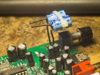
I've successfully removed the two caps on the DAC outputs, just before the potentiometer, and soldered a pair of Rubycon 100uF 50V caps I happened to have in my bits box to the positive solder pads, with the negative leads floating so I can connect two wires to them which will lead to the output RCAs.
So now I need to solder on a couple of wires to the USB pins for a 5V supply, which I shall do shortly.
Pics to follow, camera battery is charging.
This is just a 'turn some of my pile of 'junk' bits into something useful and learn a bit of practical experience in the process' project, as I definitely need to improve my skills and experience before working on some more valuable pieces of kit.
Here's some potentially stupid questions:
I have a LM7812 regulator board, and according to the datasheet, the rated output of this reg is 12V, 1.2A. I assume this is the maximum value and if I feed it 6v, it will still work and give me 6v out (minus a slight V drop)?
L7812 LM7812 Three Terminal Regulator Module 12V Voltage Power Regulator Module 656007997159 | eBay
I have a load of 2200uf 16v caps and I was thinking I would use a few of them as smoothing caps after the regulator. I read that you should parallel a much lower value cap, preferably a poly type, to preserve high frequencies. I have some 1nF poly caps, and some 1000pF poly caps, isn't 1000pF the same value as 1nF, i.e. 1000 pico farads = 1 nano farad? Would a cap of this value be suitable for paralleling to a bunch of smoothing 2200uf electrolytics or do I need something even lower in value?
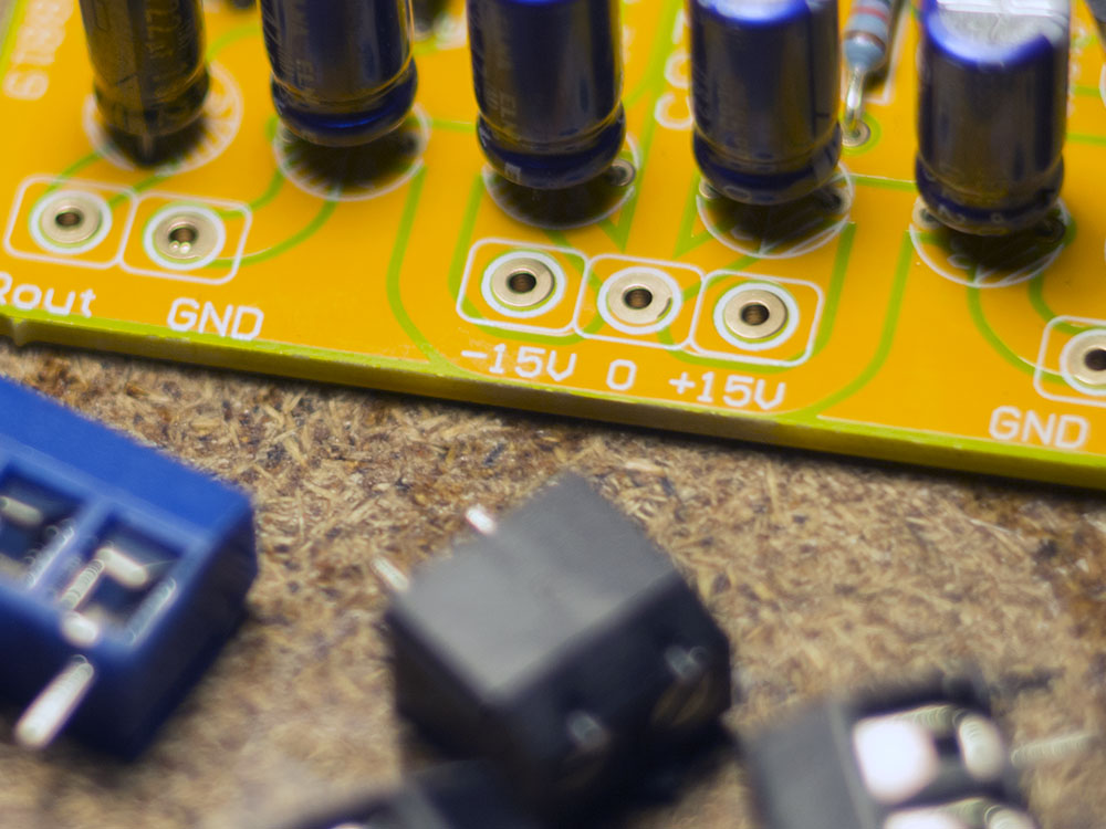
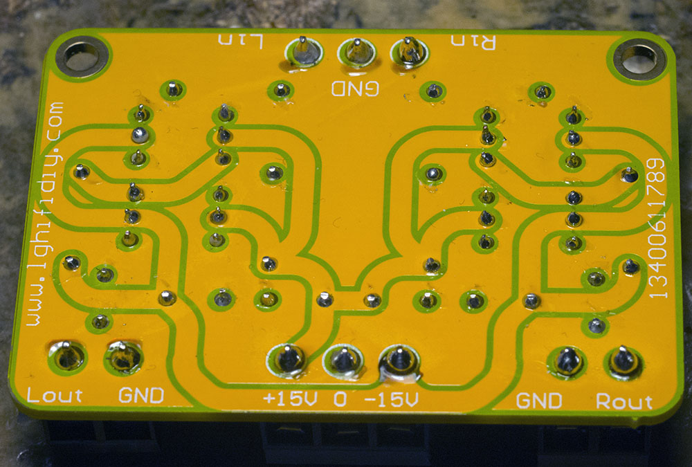
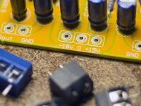
The transformer I'm using also has a secondary winding that gives 15v output. I also happen to have a diamond buffer card that runs off 15V. It has three terminals marked +15V, GND and -15V. Does this mean I can run this board directly off the 15v AC by using the +15v and -15v terminals or do I need to rectify the AC into DC and pass it through a regulator and some smoothing caps in order to power the buffer? If I do so, then I would use the +15V and GND connections?
I have a LM7812 regulator board, and according to the datasheet, the rated output of this reg is 12V, 1.2A. I assume this is the maximum value and if I feed it 6v, it will still work and give me 6v out (minus a slight V drop)?
L7812 LM7812 Three Terminal Regulator Module 12V Voltage Power Regulator Module 656007997159 | eBay
I have a load of 2200uf 16v caps and I was thinking I would use a few of them as smoothing caps after the regulator. I read that you should parallel a much lower value cap, preferably a poly type, to preserve high frequencies. I have some 1nF poly caps, and some 1000pF poly caps, isn't 1000pF the same value as 1nF, i.e. 1000 pico farads = 1 nano farad? Would a cap of this value be suitable for paralleling to a bunch of smoothing 2200uf electrolytics or do I need something even lower in value?
The transformer I'm using also has a secondary winding that gives 15v output. I also happen to have a diamond buffer card that runs off 15V. It has three terminals marked +15V, GND and -15V. Does this mean I can run this board directly off the 15v AC by using the +15v and -15v terminals or do I need to rectify the AC into DC and pass it through a regulator and some smoothing caps in order to power the buffer? If I do so, then I would use the +15V and GND connections?
Some pics:
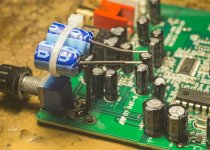
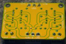
Here's how I installed the pair of Rubycons for DC filtering after removing the two caps onboard, which means the volume pot and the onboard outputs and the headphone amp is not connected anymore.


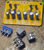
Here's the output buffer board, which I will probably have to use to reduce the high impedance of the Cirrus DAC's output, I added screw terminals and my soldering is getting neater,which is a large part of why I am doing this simple build - to get some much needed practice and improve my skills while also learning much that will prove useful for my next, better build.

Here's how I installed the pair of Rubycons for DC filtering after removing the two caps onboard, which means the volume pot and the onboard outputs and the headphone amp is not connected anymore.
Here's the output buffer board, which I will probably have to use to reduce the high impedance of the Cirrus DAC's output, I added screw terminals and my soldering is getting neater,which is a large part of why I am doing this simple build - to get some much needed practice and improve my skills while also learning much that will prove useful for my next, better build.
Attachments
Here's some potentially stupid questions:
I have a LM7812 regulator board, and according to the datasheet, the rated output of this reg is 12V, 1.2A. I assume this is the maximum value and if I feed it 6v, it will still work and give me 6v out (minus a slight V drop)?
L7812 LM7812 Three Terminal Regulator Module 12V Voltage Power Regulator Module 656007997159 | eBay
Unfortunately no. Regulators don't work that way. Generally a regulator needs whatever the target voltage is (in this case 12V) plus a bit more, usually 2-3 volts. So in your case, about 15v to regulate down to 12. This is the case for the 78xx series, 317/337, etc. If you don't give them enough, they "drop out" of regulation. That's why there are a whole series of fixed voltage regulators. The 317/337 are adjustable, but need an external variable pot to perform this function.
There are newer "LDO", (Low voltage Drop Out) regulators that need less of a "buffer", but they still need more voltage input than they are expected to output.
I have a load of 2200uf 16v caps and I was thinking I would use a few of them as smoothing caps after the regulator. I read that you should parallel a much lower value cap, preferably a poly type, to preserve high frequencies. I have some 1nF poly caps, and some 1000pF poly caps, isn't 1000pF the same value as 1nF, i.e. 1000 pico farads = 1 nano farad? Would a cap of this value be suitable for paralleling to a bunch of smoothing 2200uf electrolytics or do I need something even lower in value?
The transformer I'm using also has a secondary winding that gives 15v output. I also happen to have a diamond buffer card that runs off 15V. It has three terminals marked +15V, GND and -15V. Does this mean I can run this board directly off the 15v AC by using the +15v and -15v terminals or do I need to rectify the AC into DC and pass it through a regulator and some smoothing caps in order to power the buffer? If I do so, then I would use the +15V and GND connections?
No, you can absolutely NOT do that. You need a power supply with bridge rectifiers, smoothing caps and regulators to turn the AC into DC voltages that the board can use.
Last edited:
To add about regulators, read the applications section of the data sheet(s) to see what they need in the way of smoothing caps on the input and output. It isn't just any old thing you have. Too much, too little, the wrong kind of caps, all can cause problems, depending. One must learn how to read data sheets, not all at once, but learn more and more about what everything means and what they are trying to tell you as time goes on. Read and ask, do what you have to do to learn. That's fun with electronics for you.
Last edited:
Aha, that makes perfect sense, cheers.
So, for the L7812 I have, it is a 12v fixed output, and according to the datasheet it has a min input voltage of 19v. Hmm, 7v drop, that's a lot, is that typical or is the L7812 not a very efficient regulator and others are better in this regard?
To build a 5v supply for my DAC board, I'll have to measure the output of the transformer I intended to use, let's say for argument's sake, it is 9V, then find a regulator that will produce a 5v output from a 9v input, i.e. it has a voltage drop of no more than 4v? The L7805 needs a min of 10v to produce a 5v output, so it seems t me my next step is to get the multimeter out and measure the outputs of my transformer.
Last edited:
The Farnell UK website, it says 19v min for input:
http://uk.farnell.com/stmicroelectr...hc0fUnsU9tGHmyeiSEHke20jX4zU6Q2waAmZNEALw_wcB
The datasheet gives the same, 19V input for the L7812:
http://www.farnell.com/datasheets/2...hc0fUnsU9tGHmyeiSEHke20jX4zU6Q2waAmZNEALw_wcB
http://uk.farnell.com/stmicroelectr...hc0fUnsU9tGHmyeiSEHke20jX4zU6Q2waAmZNEALw_wcB
The datasheet gives the same, 19V input for the L7812:
http://www.farnell.com/datasheets/2...hc0fUnsU9tGHmyeiSEHke20jX4zU6Q2waAmZNEALw_wcB
Last edited:
I have one of these LM317/337 boards:
LM317 LM337 AC-DC 5V 12V Adjustable Voltage Regulator Regulated Power Supply | eBay
There are two blue boxes with screws on them, which I take it is how the output is adjusted.
So, the way to use this thing would be to connect the AC from the transformer then put a meter across the outputs and adjust the screws until the meter reads the desired voltage?
 )
)I've measured the outputs on the transformer I was hoping to use, it has two 9v output wires with a common ground and a pair of wires putting out 21v.
I googled the part number and it's made by Winbond, but I couldn't find the specs. A very similar model number has two 10v lines putting out 800mA each and a 24v line putting out 65mA.
So my plan now is to get the thing running using this transformer, with no output stage other than the decoupling caps I added to the board.
Then I'll add the diamond buffer board running off the 21v line and see how that changes the sound.
Then I'll ether add a second transformer just to power the buffer or replace the transformer altogether and see if that improves the SQ.
It turns out there is more to turning AC into DC than you know. A multimeter is usually calibrated to read in RMS AC volts, even if not true RMS reading. RMS is 0.707 of the peak voltage. That peak to peak voltage is twice the peak voltage. Depending on filter caps size and rectifier types (full wave, half-wave, etc.) a range of output voltages is possible.
Also, center-tapped windings may be used as two legs and a common ground or just two legs with the center tap floating.
To see what kind of voltages can be produced you might need to look at an appropriate book or book chapter. Maybe try something like this for starters: http://www.introni.it/pdf/Motorola - Rectifier Applications Handbook.pdf
- Status
- This old topic is closed. If you want to reopen this topic, contact a moderator using the "Report Post" button.
- Home
- Source & Line
- Digital Line Level
- Upgrading cheap Cirrus Logic CS4344 24-bit, 192 kHz Stereo DAC