Hello all,
I want to start a thread about this unconventional dac chip from Philips. I see considerable amount of topics and implementations about other chips from same era (say TDA1545, TDA1543) but such interest didn't involve with TDA1387 somehow.
I wasn't aware of this dac chip until trying to find out which chip was the behind of old Creative AWE64's sound. I surprised with the existence of this eeprom look-alike small chip.
Since this dac accepts i2s signals directly, I decided to build an external dac feed by Amanero like usb/i2s interface. But I couldn't find an I/V stage (or a complete schematic of course) which specifically calculated for this dac's output capabilities and requirements. If you have any recommendations and design offers I appreciate any contributions for this thread.
Regards.
Attachments
Last edited:
I remember Creative AWE64.
Was that a non-oversampling sound-card then?
Since the chip supports up to 384khz sampling rate, we can't consider the every design based on tda1387 should be the non-oversampling. I don't know design details about AWE64 then have no idea about oversampling capabilities of it.
Thanks for opening the thread terranigma, its a great DAC chip to talk about and I've plenty of experience to share from a couple of years of playing with it.
Its a very close relative of the (older) TDA1545 but has two clear advantages for DIYers over that chip. First its I2S and second its output can go down to 0V which makes designing the I/V stage easier. In fact just a resistor to 0V is all that's needed and this sounds better than a resistor to a supply voltage within the output compliance range (which is the solution for TDA1545).
Given the wide output compliance (0-3.5V with a 5V supply) there's a wide choice of resistor values that work well. I started out using small values (50 to 100R) because of my intentions to use a following passive filter. It turns out that for lower impedances the inductor values are smaller, hence easier to wind when custom values are needed (fewer turns, less chance of losing count, thicker wire is less likely to snap).
The disadvantage of using low value I/V resistors is lower output level. This can be overcome though by stacking chips - I've stacked up to 8 so far. More recently though I've become more adept and confident at inductor winding for passive filters so have been moving towards higher impedances. Being able to delete an active amplification stage and only use a buffer and transformer I feel will bring benefits in SQ as in my experience the amp stage's power supply has been the limiting factor. A pure classA buffer I have a hunch will be less limited by power supply quality.
The arrangement I currently use is TDA1387 -> resistor to 0V -> LC filter -> AD815 post amplifier -> ferrite core trafo.
The transformer serves two useful purposes - first it converts the balanced output of the AD815 to unbalanced, second it provides noise isolation between DAC and amp. Even with a balanced input to the amp the isolation is worth winding a trafo for. Ferrite core trafos are considerably cheaper than any bought solutions, which generally use steel (cheaper) or nickel or mu-metal cores (expensive). Ferrite while having poorer flux capability than metallic cores does have the advantage of being an insulator which improves the isolation between primary and secondary.
The AD815 has a lot of attention paid to its power supply and its outputs are loaded down by current sources. I'll talk in more detail about this if there's interest.
Thank you abraxalito.
Do you drive tda1387's in balanced mode, thus 8*4 stacks for stereo? Is stacking 8 of them still not providing enough voltage swing?
Do you drive tda1387's in balanced mode, thus 8*4 stacks for stereo? Is stacking 8 of them still not providing enough voltage swing?
Yes - the stack of eight I did (as a mod to a Muse 1543 DAC) was 2 * 4 in balanced mode. I then used an AD830 to create an SE output. Sounded pretty good for an unfiltered DAC.
Stacking them doesn't increase the possible voltage swing - that's limited by the output compliance. It increases the voltage swing for a particular I/V resistor though. A single DAC can give the full voltage swing if the I/V resistor's around 3.5kohms. For a standard level CD output (which is 2VRMS) then running balanced can achieve this - followed by a 1:1 transformer to create an SE output.
Stacking them doesn't increase the possible voltage swing - that's limited by the output compliance. It increases the voltage swing for a particular I/V resistor though. A single DAC can give the full voltage swing if the I/V resistor's around 3.5kohms. For a standard level CD output (which is 2VRMS) then running balanced can achieve this - followed by a 1:1 transformer to create an SE output.
Ok, I got it now. Maybe off topic but can you go into detail about your inversion process of i2s signal please?
I have Potato PO74G74 flip flops. I plan to use them for re-clocking i2s. I wonder if these chips also capable of generate inverted signal for a particular signal.
http://www.potatosemi.com/potatosemiweb/datasheet/PO74G74A.pdf
I have Potato PO74G74 flip flops. I plan to use them for re-clocking i2s. I wonder if these chips also capable of generate inverted signal for a particular signal.
http://www.potatosemi.com/potatosemiweb/datasheet/PO74G74A.pdf
Thank you for sharing your practical experience.
I suppose 3.5V compliance does not mean it still sounds good at 3.5k R_iv ?
If you use 4x in parallel and 100R, it will only give you 0.28Vrms out.
Are you then using AD815 to make up for the gain ?
When using 5V supply, does the digital inputs have to be 5V as well, or 3.3V will also do ?
Patrick
I suppose 3.5V compliance does not mean it still sounds good at 3.5k R_iv ?
If you use 4x in parallel and 100R, it will only give you 0.28Vrms out.
Are you then using AD815 to make up for the gain ?
When using 5V supply, does the digital inputs have to be 5V as well, or 3.3V will also do ?
Patrick
For inversion of the I2S I have found a spare inverter inside my QA550 wav player amd route the data signal through it.
I haven't noticed any SQ differences correlated with the size of the I/V resistor, though its true I've never tried as high as 3.5kohm. My current implementation uses a much lower supply voltage (2.7V) which is compatible with supercapacitors - so the compliance then is about 1.2V, I'm using around 1.2kohms. Yes the AD815 is needed to make up some gain - 6dB is lost in the passive filter for a start. Its also used to correct for the NOS FR droop which is over 2dB by 18kHz (the cut-off frequency of my LC filter).
The digital inputs are nominally TTL compatible, irrespective of the supply rail - 0.8V(0) to 2V(1) does fine IME.
Yes - prior to the AD815 by putting a big cap in series with the LC filter's termination resistor.
I/V vs. I/V
That was roughly 2007 ... and then diyparadise offered a PCB+kit of Rudolf Broertjes’ SS I/V Gain Stage (originally posted here on DIYA about a decade back)... and that made quite an improvement in SQ over orig. passive I/V.
I think diyparadise further tweaked the Rudolf I/V stage per their "mojo" project. Here's how the mojo mod affected Rudolf's orig. SS I/V:
Alas, I don't know much about "mojo" as I only implemented the original Rudolf-Broertjes-ss-iv-gain-stage.
With respect to the similar TDA1545A, I originally tried a passive approach to I/V, using only resistors, and was unimpressed with the sound. I can't comment on "LC filter -> AD815 post amplifier -> ferrite core trafo" as I never went that route.The arrangement I currently use is TDA1387 -> resistor to 0V -> LC filter -> AD815 post amplifier -> ferrite core trafo.
That was roughly 2007 ... and then diyparadise offered a PCB+kit of Rudolf Broertjes’ SS I/V Gain Stage (originally posted here on DIYA about a decade back)... and that made quite an improvement in SQ over orig. passive I/V.
I think diyparadise further tweaked the Rudolf I/V stage per their "mojo" project. Here's how the mojo mod affected Rudolf's orig. SS I/V:
An externally hosted image should be here but it was not working when we last tested it.
Alas, I don't know much about "mojo" as I only implemented the original Rudolf-Broertjes-ss-iv-gain-stage.
For all such uni-polar supply DACs there is one small issue with IV circuits, namely the bias current.
That applies to a TDA1387 as much as a PCM1794.
When you place the DAC current output at Gnd, you need to drain away the bias current to a negative supply.
There are two pre-requisites for that, namely :
1. The bias current itself is stable with time and temperature.
2. The current source is also stable with time and temperature.
Or you have to use a servo to vary the draining CCS current, with all the complexity associated with it.
Of course you can deliberately allow a DC offset at the output of the IV (we have done that with our SEN IV) and use a decoupling cap.
But I always try to avoid decoupling caps as I can.
So no simple, elegant solutions ......
Patrick
I use the decoupling cap method but was surprised how it needed to be rather big to reduce the apparent colouration. I think I have something of the order of 50,000uF there now in multiple paralleled electrolytics.
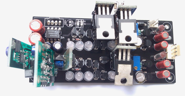
Good thread. The TDA1387 has interested many of us here for a long time. Has anyone actually ever designed and had a PCB fabricated? There seems to be very little in the market for either DIYers or finished products. Even a quick scan of fleabay shows no kits or boards, just cheap chips (which is great considering the cost of, say, the TDA1541 or PCM1704). What is the best way in to the world of the TDA1387?
Hello abraxalito,
Could you had a chance for compare vinyl release and digital release of same recording? I don't mean one to one comparison, it is enough to give some opinion if you had listen the vinyl version of recording in the past. How would you describe the sound signature of your current system? Sorry for my curiosity.
Could you had a chance for compare vinyl release and digital release of same recording? I don't mean one to one comparison, it is enough to give some opinion if you had listen the vinyl version of recording in the past. How would you describe the sound signature of your current system? Sorry for my curiosity.
I have no vinyl any longer - I divested myself of that many years ago. Describing my current system I can do - its more dynamic than any other system I can recall hearing. Although its using normal speakers the sound it produces is more reminiscent of having horns in that its effortless and doesn't get in the way of whatever music's playing. The soundstage is very deep on the right recordings and I feel drawn into listening. By which I mean the music is emotionally engaging - to me that says the perceived noise floor of the system is low so that the original recording shines through.
@lordearl - to kick off I'd suggest slap down a chip on a bit of protoboard (I use 2mm pitch and place the chip at 45degrees) and wire up a low impedance power supply from a lot of paralleled caps. Be sure to decouple pin7 with a lot of caps too. Choose your I/V resistors to suit your post-amp stage.
@lordearl - to kick off I'd suggest slap down a chip on a bit of protoboard (I use 2mm pitch and place the chip at 45degrees) and wire up a low impedance power supply from a lot of paralleled caps. Be sure to decouple pin7 with a lot of caps too. Choose your I/V resistors to suit your post-amp stage.
Ozone - Basalt edition
Here's my latest 'Ozone' DAC incarnation, the 'Basalt' taking shape. The box is one I bought from a Taobao seller a few years back when I was first dreaming of creating a DAC. At that time though I had no idea that I'd need so many capacitors on the supplies, so for this variant I'm dispensing with the AD815 stages as the caps it (the AD815) needs to optimize its dynamics simply won't fit.
The power supply is at the top, with LC filtering and MJE15035 transistors for regulation of the supplies to the two cap banks. The smaller hexacap is based on some 3.3F supercaps and powers 4 * TDA1387 in dual differential mode. On top of the larger of the two hexacaps is a balanced discrete buffer which is experimental. Still to add are the balanced LC audio filters and the output transformers. I might even add an S/PDIF interface at some point but for now its I2S in.
Attachments

UNsuper-size me!
The latest diyparadise TD1545A "mojo" ... a DIY "Manhattan" project ... is similar in CinemaScope ... err....or is that Panavision:
And I should frigg*n' talk!!!... some of my former projects with CD players and massive external PSU are 10x worse the offender ... are inconvenient ... and just (now) sit uselessly in storage ... all the while my "smartphone" or 'Pad + headphone amps/DAC (super cheap Chinese ready-made and no soldering required) get all the musical attention.
What's de rigueur in certain DIY circles is to squeeze something similarly high-performance down to something pocket-sized, with USB input, and LiPo powered. (IMO, that's very possible given modern, micro components).
So, that should be a goal of a thrill-seeking DIYer with TDA1387/1545A in mind: small, portable, battery-powered, and practical ... i.e., one used so often, as in daily playlists, that it becomes ubiquitous-in-pocket.
With all that "TLC" and INVESTED TIME tweakin' n' cajolin', I'm sure it sounds nice ... but ... this is old-style DIY: i.e., massive use of real-estate, linear pwr, etc. ...Here's my latest 'Ozone' DAC incarnation, the 'Basalt' taking shape.
The latest diyparadise TD1545A "mojo" ... a DIY "Manhattan" project ... is similar in CinemaScope ... err....or is that Panavision:
And I should frigg*n' talk!!!... some of my former projects with CD players and massive external PSU are 10x worse the offender ... are inconvenient ... and just (now) sit uselessly in storage ... all the while my "smartphone" or 'Pad + headphone amps/DAC (super cheap Chinese ready-made and no soldering required) get all the musical attention.
What's de rigueur in certain DIY circles is to squeeze something similarly high-performance down to something pocket-sized, with USB input, and LiPo powered. (IMO, that's very possible given modern, micro components).
So, that should be a goal of a thrill-seeking DIYer with TDA1387/1545A in mind: small, portable, battery-powered, and practical ... i.e., one used so often, as in daily playlists, that it becomes ubiquitous-in-pocket.
Last edited:
- Status
- Not open for further replies.
- Home
- Source & Line
- Digital Line Level
- TDA1387 continuous calibration dac