I also found paralel 4 dac chip.
but I guess it's expensive (for me)
Tekdevice Quad Philips 4X TDA1387 in Parallel 192K SPDIF Passive I V DAC | eBay
I really interest with this dac chip sound
I look at past discussion is mean passive I/V are sound better than active I/V ?
how with active I/V with opa861 some people said it the best I/V among other I/V.
according your schematic and datasheet I found
on the single ozone dac that you use
07M-332K =3.3mH
07M-333K = 33mh
and ozone dac with parelel 6 dac chip the filter value changing to
1m
SLF7045-681 (600uH)
is you have formula if that dac chip let said like we paralel to 8 or maybe 12.??
and is there have sonic differences between single dac chip and paralel dac chip on TDA1387 in term sound quality not about technical things ?
also is there have different in sound quality between use cheap inductor and expensive inductor ?
Attachments
Last edited:
The inductor values depend on the working impedance of the filter. If you want to parallel 8 DACs then scale the working impedance down by a factor of 8. With 12 DACs, divide the input and output resistors by 12. You'll also need to divide the inductor values and multiply up the capacitor values by the same factor.
I'd suggest with 8 DACs, use 3.3mH and 330uH inductors, 270R resistors. With 12 DACs, use 2.2mH and 220uH, 180R resistors.
Cheaper inductors tend to have higher losses, this will give you a premature HF roll-off which may well be audible. They're also less likely to be screened so will pick up hum.
I have not done a comparison between multiple DACs and a single DAC. So far I've always used multiple DACs and got great sound. But its entirely possible that a single DAC may sound even better because the SQ is largely determined by the power supply. I plan to build a paralleled DAC where each chip has its own power supply, rather than stacking chips fed from the same power supply. Then I'll be able to compare.
No, I'm only interested in passive I/V conversion so haven't tried any active solutions. In my estimation passive filtering produces lower IMD than active.
If you want to combine it with a filter yes you can, but the filter must be on the output of the OPA861. Its rather a heavy load to drive so I doubt it'll sound great unless you pay a lot of attention to the OPA's power supply impedance and bias its output stage into classA.
If you want to combine it with a filter yes you can, but the filter must be on the output of the OPA861. Its rather a heavy load to drive so I doubt it'll sound great unless you pay a lot of attention to the OPA's power supply impedance and bias its output stage into classA.
The arrangement I currently use is TDA1387 -> resistor to 0V -> LC filter -> AD815 post amplifier -> ferrite core trafo.
ferrite core trafo is mean trafo out for this dac ?
can you post the photo ?
is you buy ready made or DIY winding ?
and what mean resistor to 0V ?
sorry I had a lot question because I have little knowledge in electronics.
I haven't any photos to hand of the transformers, but I'll take one and post it up in the next few days. I wound them myself, PQ25 cores (I think). The core isn't very critical though.
Resistor to 0V means a resistor between pin6 and pin4. Another between pin8 and pin4 (for the other channel).
Resistor to 0V means a resistor between pin6 and pin4. Another between pin8 and pin4 (for the other channel).
it is nice and interesting to build.
is this filter can applied another dac ? did you try this filter to another dac ?
and is there have sonic differences when use filter and without filter ? because is not kind of easy to found in market compare to TDA1545 and TDA543, and is this dac sound better than TDA1545 and TDA5143 ? or maybe TDA1541A
Thanks for your encouragement
You could apply this filter to another DAC certainly. I've not yet listened to the particular filter you mentioned, rather one with the same topology but different values. I've not tried another DAC than TDA1387 though I'd expect TDA1545A to sound pretty much identical (but for the extra supply needed to maintain the correct compliance voltage). I gave up on the TDA1543 a few years ago, its not as transparent as 1387/1545.
As for TDA1541A I've not given that a serious listen - I'd hope its better than 1387 in an optimum implementation and I'd also hope its far less power supply sensitive. But its so power-hungry I'm not interested in developing circuits with it for now.
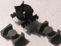
I've temporarily mislaid the last pair of DAC output trafos I wound, so here's a pic of some of the ingredients - the two PQ25 core halves and the bobbin behind. The '25' in the name is the width of them - 25mm.
If anyone wants to know the equation needed to get designing with these, just ask. Once the right number of turns have been wound on (I'm so lazy I can't be bothered to count, I check the ratio with a siggen and AC voltmeter) then I strap them together with yellow transformer tape.
If anyone wants to know the equation needed to get designing with these, just ask. Once the right number of turns have been wound on (I'm so lazy I can't be bothered to count, I check the ratio with a siggen and AC voltmeter) then I strap them together with yellow transformer tape.
Attachments
I also found paralel 4 dac chip.
but I guess it's expensive (for me)
Tekdevice Quad Philips 4X TDA1387 in Parallel 192K SPDIF Passive I V DAC | eBay
I really interest with this dac chip sound
I look at past discussion is mean passive I/V are sound better than active I/V ?
how with active I/V with opa861 some people said it the best I/V among other I/V.
Hmmm, I'm not sure I like the 4X.


4 chips are sharing one sm bypass and OSCON?!?
This is how I'd redo it (w OSCONs over each sm bypass) but for the last 3 chips, the sm cap connects to a small gnd island that is attached to the back gnd plane by one tiny via.

Hmmmm, not sure that's right...
What thinks you ('braxy)?
However, it looks like they still have the single 1387 at the tecdevice website:
TDA1387 I2S DAC Module Passive Resistor I/V

And their WW8804 does I2S (1387) and 1545 input:

Wolfson WM8804 SPDIF Module Support 16/24Bit I2S Left/Right Justified
GPO0=0 SDOUT=0 >> 16Bit I2S
GPO0=0 SDOUT=1 >> 24Bit I2S
GPO0=1 SDOUT=0 >> 24Bit Left Justified With Flags
GPO0=1 SDOUT=1 >> 16Bit Right Justified
hmmm, ....
Last edited:


I've been using their single TDA1545a board for a while with great results. In fact, the treble on the TDA1545 is spectacular, unmatched in my opinion.
On that basis I've ordered one of the 4x TDA1387 units, will post more when I've powered it up and use it to determine just how bad the new Pink Floyd album really is.
On that basis I've ordered one of the 4x TDA1387 units, will post more when I've powered it up and use it to determine just how bad the new Pink Floyd album really is.
I've been using their single TDA1545a board for a while with great results. In fact, the treble on the TDA1545 is spectacular, unmatched in my opinion.
On that basis I've ordered one of the 4x TDA1387 units, will post more when I've powered it up and use it to determine just how bad the new Pink Floyd album really is.
I guess you should try network filter and transformer out like abrax doing
I've asked TekDevice for some details on the 4x tda1387 unit.
So the iv resistor is 1.2k and the output is about 1.5vrms.
There's also 22uf bypassed with 0.1uf at the pin 7 ref (whatever that means).
Abraxalito - what should I reduce the iv resistor to in order to try a transformer output?
I have a pair of transformers to try with the following specs:
For Passive I/V of DAC
Low Copper Resistance
Low Distortion
High Level Capability
Nickel Permalloy Core
Mu-Metal Shield
1. 20 Ω : 600 Ω (CT 150Ω) 1:5.48(2.74)
2. Distortion (THD) : <0.001% @1KHz
3. Frequency Response : 5 ~ 100KHz(-3db)
4. Power Level : MAX +24dBu @20Hz
5. Transformer Size : 30 x 24 x 18(W x D x H : mm)
You want the same output voltage level as now (1.5VRMS)?
If so then divide 1.2k by 5.48 (the voltage ratio) - I get 220R. If you want standard CD output (2VRMS) then you'd need 300R.
Incidentally you may well notice better bass if you increase the Vref (pin7) bypass cap. Sky's the limit but don't use Oscons as they're leaky.
If so then divide 1.2k by 5.48 (the voltage ratio) - I get 220R. If you want standard CD output (2VRMS) then you'd need 300R.
Incidentally you may well notice better bass if you increase the Vref (pin7) bypass cap. Sky's the limit but don't use Oscons as they're leaky.
If you want standard CD output (2VRMS) then you'd need 300R.
Probably a good idea to keep it to the standard 2vrms which would bypass the need for a preamp.
Although with 300r as the iv, won't the output impedance be about 9k?
My power amp has an input impedance of 47k, which means the output impedance of the transformer stage shouldn't be more than 4k7.
4k7 / 30 gives an iv of 150r.
What vrms would we get using an iv of 150r?
If you omit the preamp then the DAC's output should correspond with the input sensitivity of your poweramp. That's normally never as high as 2V, typically 0.7-1.0VRMS, If you like to listen loud though and don't mind some clipping then you could go for up to 2VRMS.
Yes you're right with 300R for I/V the output impedance will be 9k. 150R gives 1VRMS output - so then you'll avoid clipping your poweramp most likely. If you do want to listen loud I'd suggest buying four more TDA1387s and stacking them on top of the current ones.
Yes you're right with 300R for I/V the output impedance will be 9k. 150R gives 1VRMS output - so then you'll avoid clipping your poweramp most likely. If you do want to listen loud I'd suggest buying four more TDA1387s and stacking them on top of the current ones.
- Status
- This old topic is closed. If you want to reopen this topic, contact a moderator using the "Report Post" button.
- Home
- Source & Line
- Digital Line Level
- TDA1387 continuous calibration dac