The question would seem to be whether or not low-offset frequency (close-in) phase-noise is more encoded in the sine wave part of a clock signal or if it is encoded in the higher frequency harmonics.
Seems to me the harmonics that exist in relation to clock edge rise time probably correspond to high-offset frequency phase noise, aka jitter. That is to say, low-offset frequency phase-noise is a slight time compression or rarefication of the fundamental sine wave over time. Its a rotating vector that is slightly speeding up and slowing down as it rotates.
Also, as a reminder, low-offset frequency phase-noise is of particular interest because clock phase-noise is approximately convolved with the audio signal and the result of that due to close-in phase noise exists in the audio band.
Last edited:
Arrogant a$$hole, episode 2:
Dude!!!!!!!
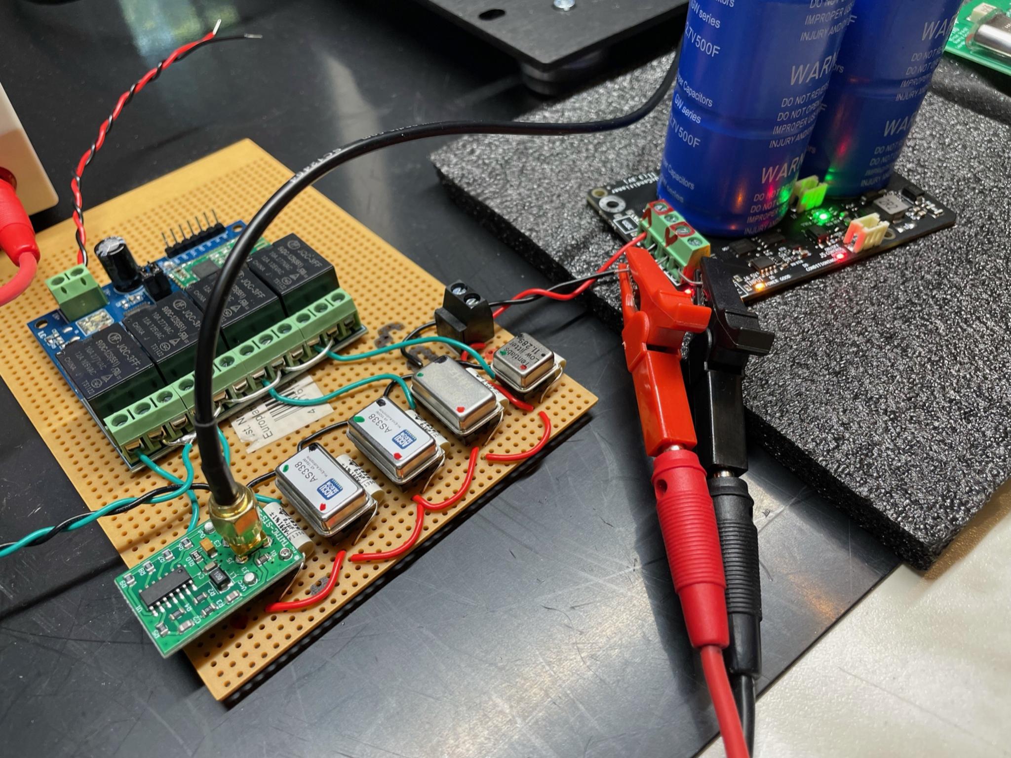
HF running through flying wires and relays, no ground plane, no decoupling, no filtering, no shielding, no ferrites, all the clocks are ON at the same time so they will lock, no source termination, and you draw conclusions based on this setup?
Dude!!!!!!!
HF running through flying wires and relays, no ground plane, no decoupling, no filtering, no shielding, no ferrites, all the clocks are ON at the same time so they will lock, no source termination, and you draw conclusions based on this setup?
Another point: did You see this?
https://www.diyaudio.com/forums/gro...-ultra-low-jitter-clock-gb-6.html#post6684281
Interesting find!
Though, today it's not the size that count..
https://www.diyaudio.com/forums/gro...-ultra-low-jitter-clock-gb-6.html#post6684281
Interesting find!
Though, today it's not the size that count..
Arrogant a$$hole, episode 2:
Dude!!!!!!!
HF running through flying wires and relays, no ground plane, no decoupling, no filtering, no shielding, no ferrites, all the clocks are ON at the same time so they will lock, no source termination, and you draw conclusions based on this setup?
yes, no problem at all. the differences are clearly audible and consistent.
So, when all is nicely done, it can only be a tad better. Or do you believe that when all those things you mention (when 100% in place) the XO standard clock suddenly outperforms Andrea clock?
As I said several time if you would measure the jitter of low noise clock you have to buy a phase noise analyzer.
I can assure you that it is an excellent, albeit expensive, investment.
Andrea
TimePod 5530A is a $4995- low cost phase noise analyzer.
Really don't understand why you always try to convince others that it's an expensive equipment.
"John Miles
TimePod 5330A is shipping, and it's available at lead times from one to six weeks, depending on quantities ordered and parts/production scheduling at this end. The current price is US $4995.00 each for 1-5 units."
TimePod 5330A announcement/info (was TimePod, cross-correlation fun and measurements)
I really don't like money is involved in a technical discuss. Sorry about that.
Ian
That was the price nine years ago. What do they cost today? $20,000? Rent or Buy Microsemi 53100A Phase Noise and Allan Deviation Tester, 1 to 200 MHz
Last edited:
Hi Ian,
it seems to me that now you want to climb the mirrors.
It is not a question of the cost of the tool, what matters is the operating principle and what it can measure correctly.
I seem to have explained this quite clearly in the previous post, the Timepod approach to the phase noise measurement is the same of the FSWP, except the Timepod does not implement a down converter and so the DUT upper frequency limit is 30 MHz.
The Timepod, but now it's the Microsemi 3120A, uses 4 x LTC2216 AD converters with 16 bit resolution running with 80 MSamples/s. It achieves a signal to noise ratio (SNR) of about 82 dB relative to full scale.
Not much different from the FSWP that uses AD converters with 16 bit resolution running with 100 MSamples/s. It achieves a signal to noise ratio (SNR) of about 84 dB relative to full scale.
Then both use cross correlation software.
BTW, the price you have pointed out is the first version sold directly by John Miles.
The Timepod no longer exists, John has sold his project a long time ago.
Now you have to ask Microsemi for a 3120A, which is the same tool but it costs much more.
In 2015 the price was around 20000 USD
Oscillator Phase Noise?
Andrea
Hi peufeu,
no need of medieval duel, as I said I would be happy to try another sine to square converter better than our.
But when it comes to measurements it's pretty clear that you can't measure a device that has a jitter of 1ps with a tool that has a jitter floor of 2ps.
The time will come when we will also measure the DAC output, as soon as the front end and DAC are ready.
It's a bit premature now.
Andrea
yOr do you believe that when all those things you mention (when 100% in place) the XO standard clock suddenly outperforms Andrea clock?
Most likely not, but I'd say your setup will give unpredictable results when comparing between all the other clocks, since they'll interfere with each other. If they all use the same power supply, and have different frequencies, and if they're all on at the same time, there will probably be beat tones on the power supply at the difference between each clock frequency ; that will add phase noise to each clock. If they're different brands of clock of the same label frequency, the actual frequencies will differ slightly, so the beat tones will be in the audio band, unless they all lock together.
Andrea's clock is on another board so I guess it won't couple through the power supply, which means it'll have an unfair advantage. It would probably win anyway without the unfair advantage though.
I would suggest getting for a really modest price a TinySA tinySA | Main / HomePage (less that $100) and look at the radiation. Its hard to show a direct connection between the EMI coming from the clocks (and other layout challenges) and the final audio, I think its safe to say making a serious effort to control the radiation and isolate the radiators from the sensitive audio stuff cannot hurt the system. This and the NanoVNA are pretty amazing tools for not much $$$. Learning how to use them well will take study and experimentation but it can remove a lot of guesswork and show a lot of stuff to look at. A set of probes will also help https://www.amazon.com/Electronic-C...ywords=near+field+probe&qid=1623202955&sr=8-9 I have a premium set and I may get one of these sets so I can compare to gauge utility.
The question would seem to be whether or not low-offset frequency (close-in) phase-noise is more encoded in the sine wave part of a clock signal or if it is encoded in the higher frequency harmonics.
Seems to me the harmonics that exist in relation to clock edge rise time probably correspond to high-offset frequency phase noise, aka jitter. That is to say, low-offset frequency phase-noise is a slight time compression or rarefication of the fundamental sine wave over time. Its a rotating vector that is slightly speeding up and slowing down as it rotates.
Also, as a reminder, low-offset frequency phase-noise is of particular interest because clock phase-noise is approximately convolved with the audio signal and the result of that due to close-in phase noise exists in the audio band.
I would suggest that this can be tested for. if one takes a low frequency sine or square digital input and then measure the cycle to cycle variation and add phase noise to the master clock you should be able to see it. You would need a time interval analyzer to see the variation. The scale and its audibility may suggest this is futile but without testing you cannot know.
Which reminds me that phase noise translated to jitter is one of many ways to look at jitter. And its an average of jitter over time. it does not give an indication of peak cycle to cycle or cycle to mean values, which may be important. Measuring those values is not easy to sub-picosecond level.
One aspect overlooked when discussing the timepod (and the other digitizing tolls like a scope) is the need to filter out harmonics above 1/2 the same rate or they mix with the sample clock and generate a lot of spurious garbage. They all will have a low pass filter. And these all look for a reference crossing to do the calculations. I suspect they use an algorithm to calculate exactly when the transition happens. The shape of the wave should not be significant. The HP uses mixers to downconvert to its internal baseband and low pass filters on the output.
You can get the same or better performance with the traditional zero beat + mixer conversion. Two of these plus some correlation app on a PC and you can get the same info for a fraction of the cost of one of these analyzers. https://wenzel.com/library/time-fre...stems-hints-and-tips/phase-noise-measurement/ and this has lots of background https://tsapps.nist.gov/publication/get_pdf.cfm?pub_id=105598
I would suggest getting for a really modest price a TinySA tinySA | Main / HomePage (less that $100) and look at the radiation. Its hard to show a direct connection between the EMI coming from the clocks (and other layout challenges) and the final audio, I think its safe to say making a serious effort to control the radiation and isolate the radiators from the sensitive audio stuff cannot hurt the system. This and the NanoVNA are pretty amazing tools for not much $$$. Learning how to use them well will take study and experimentation but it can remove a lot of guesswork and show a lot of stuff to look at. A set of probes will also help https://www.amazon.com/Electronic-C...ywords=near+field+probe&qid=1623202955&sr=8-9 I have a premium set and I may get one of these sets so I can compare to gauge utility.
Thanks 1audio, will buy it.
Ian
Hi Andrea,
I have neve questioned your phase noise measurement on the sine clock signals. What I’m questioning is your phase noise measurement on square waves. If you take a look at the TimePod schematic (please see the first picture) you will know that all input signals will go through the 27MHz low pass filters first before being fed into the ADC. That means a 22.5792MHz square wave clock signal will be converted into a fundamental frequency sine wave by TimePod before taking the measurement. Because all other square wave related information was lost when converting square wave into sine wave, your TimePod will have the same phase noise result for all the three different signals in the second picture attached.
The first signal is the fundamental frequency pure sine wave clock. The second signal is a poor quality square wave clock with slower slew rate, and ringing and noise over logic levels. The third one is a better square wave clock that we can find in the real world. Those three clock signals will run a DAC at totally different quality levels, but your TimePod will never tell the difference in between.
I also attached the SXLP-27 LPF data sheet. Seems the performance is not perfect. There are a lot of leakages above the cut-off frequency. 36-41MHz has 20dB loss, above 41 MHz has 40 dB loss. For the TimePod 16bit 81.5dB ADC, the leakages will become aliasing noise which will result in worse noise floor.
Based on this issue, if your point is that the square wave quality doesn’t matter for phase noise, then why don’t you use the sine wave clock directly for a DAC without converting it into square wave?
Actually, the final output square signal quality is the most significant thing of a sine to square converter. That’s all the purpose it works for. But the quality of the square wave signal will need time domain measurement to figure out. That’s what I’m working on. My LeCroy LC584AXL is the correct equipment to use for this kind of time domain test, that’s not a question.
What I’m suspecting is that the performance of the STS sine to square board may limit the sound quality of your great DIRXO sine clock. My LC584AXL testing results also support this point, please visit the link below for more details:
https://www.diyaudio.com/forums/dig...mate-weapon-fight-jitter-664.html#post6678025
That's the reason why I decided to design a better quality sine to square wave converter for FifoPi by myself. Hopefully there will be new improvements.
Ian
Attachments


Last edited:
Hi Ian,
you keep with the wrong reasoning, you are still confusing phase with frequency.
Where the noise has reached the noise floor the phase noise becomes flat.
For input frequency below 30 MHz this happens below 1 kHz.
That's the reason why the Timepod measures the phase noise with an offsets from 0.01 Hz to 100 kHz from the carrier.
Therefore an LPF with a corner frequency at 27MHz does not affect the measurement with the above offset range, and then the integrated jitter is computed correctly.
Even a sine wave oscillators has harmonics and you claim the Timepod can measure sine wave signal but not square wave signals.
So there is something wrong with your reasoning.
Please, take a look at the harmonics spectrum of the DRIXO oscillators at 22.5792 MHz and 5.6448 MHz.
There are a lot of harmonics, the 2nd harmonic of the 22.5792 MHz XO is -31dB and it's filtered by the LPF since it lies at 45MHz. The third harmonic is -32 dB and lies at 67 MHz.
While the first 5 harmonics of the 5.6448MHz XO are not attenuated by the LPF because they lie below the 27MHz corner frequency.
So in your opinion the Timepod correctly measures a 5MHz XO but not a 22MHz XO?
Do you think the state of the art R&S FSWP tool digitizes the harmonics when measuring a 1GHz XO?
This tool is capable of measurements up to 50 GHz, do you think it uses the second harmonic at 100GHz to measure phase noise and jitter?
It looks like you have not understood how the tool works.
The R&S FSWP uses direct down-conversion of the DUT signal with a low phase noise local oscillator and an analog IQ mixer. The signal is then captured with AD converters with 16 bit resolution running with 100 MSamples/s.
Do you know how a down converter works?
The analog mixer create itself a lot of harmonics, so the combined signal coming out from the mixer has to be filtered with a LPF to reject the unwanted harmonics.
After the LPF the signal is captured with AD converter.
As I already said the measurement approach is the same, the only difference is the input frequency limit.
Since the FSWP accept input frequency up to 50GHz the offset frequency range from the carrier is wider, 30MHz vs 100kHz of the Timepod.
The reason is simple, at such high frequencies the noise floor is reachead at much higher frequency than 1kHz, so the FFT have to use a wider offset range.
Is that clear now?
The Timepod can measure a square wave just like a sine wave, the only limit is the input frequency up to 30MHz, while the FSWP accepts input frequencies up to 50GHz.
Please, try to understand how these tool work, then all will be clear.
Why?
Because oscilloscopes have a jitter floor they can't measure below, which is typically in the range of picoseconds for general scopes. There are very high-end oscilloscopes that can measure down to 100 femtoseconds of jitter. They can be very expensive, hundreds of thousands of dollars. Due to their high cost access is often limited if at all.
Fortunately, phase noise techniques can measure jitter with excellent sensitivity. Jitter measurements well below 10 femtoseconds (1 fs = 10-15 s) are possible, which is much more sensitive than a typical oscilloscope. To get this level of sensitivity the cost of a phase noise analyzer is almost two orders of magnitude lower. It is relatively easy to measure jitter under 10 femtoseconds with a phase noise analyzer.
Another advantage is that phase noise plots make it easy to distinguish random and deterministic jitter, which is difficult using an oscilloscope.
Your oscilloscope has a jitter floor of 2ps or maybe more, so you can't measure below, there is no way.
Andrea
Attachments


Last edited:

Continuing to think about the issue, square waves minimize the chances of amplitude noise affecting the time at which a switching threshold is crossed. If a phase noise measurement system can ignore amplitude noise, then square waves should be no different from sine waves for the purposes of phase noise measurement. That's because amplitude noise and phase noise are conceptually orthogonal to each other.
OK, stop me if I'm wrong
The Timepod measures phase noise embedded in the clock signal, that's pretty much the jitter you'd get at the DAC if the sine was turned into a square by a perfect noiseless comparator that doesn't care about slew rate.
And Ian says (misquoting but you get the idea) "it's not a perfect noiseless comparator, so slew rate matters, the DAC clock input gate will add its own noise, so you want high slew rate (low risetime) to minimize that"...
I think you're both right, but since you're talking about different stuff, chaos ensues 😀
Example:
All three different signals would have the same phase noise (except HF noise that was removed by the LPF). I think the TimePod would correctly give the same measurements for the three.
The scope should measure the same jitter on all three signals also (again, except HF noise removed by the LPF), but it won't, because due to its own noise slew rate will matter.
For the same reason they would result in different jitter at the DAC due to different slew rate. That depends on the internal circuitry of the DAC and how much noise there is on the power supply that controls the logic level threshold.
You could use a logic gate after the sine-to-square as an approximation for the DAC clock input, and measure that with the TimePod, and you'd probably notice a rise in noise floor depending on output slew rate of the sine to square converter.
The Timepod measures phase noise embedded in the clock signal, that's pretty much the jitter you'd get at the DAC if the sine was turned into a square by a perfect noiseless comparator that doesn't care about slew rate.
And Ian says (misquoting but you get the idea) "it's not a perfect noiseless comparator, so slew rate matters, the DAC clock input gate will add its own noise, so you want high slew rate (low risetime) to minimize that"...
I think you're both right, but since you're talking about different stuff, chaos ensues 😀
Example:
a 22.5792MHz square wave clock signal will be converted into a fundamental frequency sine wave by TimePod before taking the measurement. Because all other square wave related information was lost when converting square wave into sine wave, your TimePod will have the same phase noise result for all the three different signals in the second picture attached.
All three different signals would have the same phase noise (except HF noise that was removed by the LPF). I think the TimePod would correctly give the same measurements for the three.
The scope should measure the same jitter on all three signals also (again, except HF noise removed by the LPF), but it won't, because due to its own noise slew rate will matter.
For the same reason they would result in different jitter at the DAC due to different slew rate. That depends on the internal circuitry of the DAC and how much noise there is on the power supply that controls the logic level threshold.
You could use a logic gate after the sine-to-square as an approximation for the DAC clock input, and measure that with the TimePod, and you'd probably notice a rise in noise floor depending on output slew rate of the sine to square converter.
Is not the purpose of using a square wave vs sine dependent on the ability of the receiver to switch consistently at the same time? If the receiving device switches reliably at the precise moment the sine crosses zero, then the sine would be the perfect signal input. But we convert to a square wave to remove that uncertainty. A perfect square would then be best. But there is no perfect square wave. Is not the question how much slew is acceptable to ultimately affect sound quality? Perhaps this is why some DACs are more sensitive to clock signal than others?
I understand that this question may be too elementary, but it is one where I would appreciate some scholarly insight.
I understand that this question may be too elementary, but it is one where I would appreciate some scholarly insight.
"But there is no perfect square wave. Is not the question how much slew is acceptable to ultimately affect sound quality?"
This is the crux of the matter for me. Acceptable and desirable even. I can't contribute to the technical debate but I do know this.
Digital audio is mixed signal. Audio and RF.
Audio hates RF, it does so much damage, but we are stuck with it so SYSTEM design becomes the most important thing. This debate is focussed on measuring first order effects, the integrity of the clock signal. But it is the second order effects that also have such an impact on the SYSTEM. The insight into the TDA1541A is a perfect example. Condition the serial going into the chip reducing voltage and rise time and you get less ground bounce and another veil drops away. A perfect square wave actually provokes worse performance. How things interact in the SYSTEM is key. And we all have different systems...
- Home
- Source & Line
- Digital Line Level
- Asynchronous I2S FIFO project, an ultimate weapon to fight the jitter