Hi peufeu,
the 74AC04 as a sine to square converter has been measured many time in the RF circuit, and its residual noise is well known.
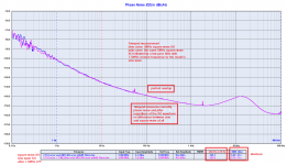
I attach a plot of the phase noise measured with the old HP 3048.
Noise floor of the tools aside (the old HP 3048 has higher noise floor) the residual noise is the same we have measured with the Timepod.
If anything, HP 3048 measurement is optimistic against the Timepod.
Andrea
the 74AC04 as a sine to square converter has been measured many time in the RF circuit, and its residual noise is well known.
I attach a plot of the phase noise measured with the old HP 3048.
Noise floor of the tools aside (the old HP 3048 has higher noise floor) the residual noise is the same we have measured with the Timepod.
If anything, HP 3048 measurement is optimistic against the Timepod.
Andrea
Attachments
I would suggest getting for a really modest price a TinySA tinySA | Main / HomePage (less that $100) and look at the radiation. Its hard to show a direct connection between the EMI coming from the clocks (and other layout challenges) and the final audio,
Hello,
Once more it looks like getting the best results also depends a lot on the '' physical postion '' of ALL the elements you will end up needing in a DDDAC unit with fifopi, raspberry, supercap, lifepo4 all combined INSIDE one chassis.
The stationpi board from Ian is a good start to have fifopi and raspberry properly connected AND also offering reduction of mutual '' interference '' while still being close.
I will kind of '' develop '' a construction that will allow the lifepo4 board to be mounted under the station pi and allow the use of several ultracap boards that will All end up with a short connection to the lifepo4 board and the 5 and 3,3 volt dc input and all the boards. Mounting everything on the '' same level '' will create to much surface to be needed and long wires all over the place. I think from a technical point of view these items should be mounted inside a metal frame.
My idea of giving each board a separate lifepo4 and supercapboard was to get maximum separation by not letting them same the same supply.
The 6 clock boards from Andrea will be in a collection of six aluminium so called stomping boxes because they are very likely to interfere when being in the same chassis as the rest. The physical distance between the stomping boxes and the BIG DDDAC chassis wont be big but there is a lot of metal in between them.
Greetings, eduard
Yeah, that doesn't look like a very good experimental setup. Sorry.
Hello,
As Doede explained this is just for a basic comparison. If you worry so much about this take a look how most people here using a set up that looks like a bad idea how not to do it.
They spend loads of money on parts and then they attach it to a board in a way with no logic involved.
Greetings,Eduard
Trying to get the most out of TWTMC clocks for FifoPi system (5)
Summarize my points so far.
1. ITimePod sine wave phase noise measurement results can be trusted. It’s a good phase noise analyzer to measure signals from 0.5 to 30MHz.
2. TimePod square waves measurement could not be that reliable, because the built-in 27MHz LPFs convert square waves into sine waves before measurement. Since all square wave related information was lost, TimePod can not tell the real quality of a square wave signal. The results tend to have better close-in phase noise and worse phase noise floor than it should be.
3. Based on Andrea’s phase noise testing results, DIRXO (sine wave) is a great oscillator. I had a big hope on it. However, by comparing it with a Pulsar OCXO, the DIRXO/STS combination does not sound as great as I expected. I suspect the STS performance was not good enough.
4. I did a jitter comparison test in the time domain to a 22.5792 MHz DIRXO/STS combo. The result shows that DIRXO/STS combination has 2ps more RMS time jitter than the same frequency CCHD957. It could be reasonable because Andrea had confirmed that CCHD957 was measured having lower phase noise floor. But I think 2ps more RMS time jitter at 5 ps jitter levels could be too high for a good clock like a DIRXO.
5. So, I carried on the direct waveform test. Time domain waveform analysis told more of the story. It shows that the STS output waveform is not perfect. It has a slower slew rate that will modulate more AM(voltage) noise into phase noise at the DAC side. And both high and low levels have ringings and ripples which can introduce more EMI noise into a DAC.
6. The reason is still not clear, but it seems that besides the close-in phase noise, the time domain signal quality and phase noise floor around 1KHz can also affect the DAC sound quality. So to ensure best possible clock quality, phase domain measurements and time domain measurements would be both important.
7. I was looking for some improvements, but Andrea told me that his STS was perfect and there is no solution to improve. Seems he had never tried doing any time domain test to his STS. And also his TimePod is not capable of telling him the square wave signal quality because square wave was converted into sine wave by the LPF.
8. In this case, I have to try to design a better possible sine to square converter by myself for FifoPi to match the good DIRXO sine clock.
Ian
Other links
1. https://www.diyaudio.com/forums/dig...mate-weapon-fight-jitter-657.html#post6668751
2. https://www.diyaudio.com/forums/dig...mate-weapon-fight-jitter-660.html#post6671042
3. https://www.diyaudio.com/forums/dig...mate-weapon-fight-jitter-662.html#post6675622
4. https://www.diyaudio.com/forums/dig...mate-weapon-fight-jitter-664.html#post6678025
The internal resistance of the Lithium-titanate battery is lower, and the electrical properties of the LTO are very close to the capacitor, so that the LTO can be charged quickly, and it is actually more suitable as an audio power supply.
I will share my experience after completing a series of tests.
I will share my experience after completing a series of tests.
Hi Ian,
I hate to repeat myself, but since your assumptions are far from the reality I have to do it.
We have already demonstrated that the Timepod measures correctly square wave oscillators, let me recall here.
We have measured the phase noise of a 5 MHz CMOS output CTS oscillator with and without a low pass filter with 7.5 MHz corner frequency before the input of the Timepod to suppress the harmonics above its fundamental.
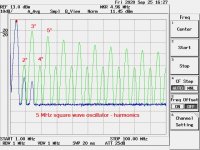
The first picture shows the spectrum analysis of the square wave at 5 MHz without the input filter (green curve) vs the same square wave with the filter at 7.5 MHz (blue line).
As you can see the spectrum of the signal without the low pass filter is charged with lot of harmonics, while inserting the low pass filter the harmonics practically disappear.
This means that the first 4 harmonics (10MHz, 15MHz, 20MHz and 25MHz), which have the higher energy, are not attenuated by the Timepod LPF at 27MHz.
They are captured by the ADCs exactly as are, so there is no conversion into sine wave.
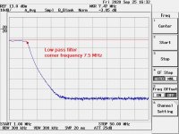
The second picture shows the AC characteristic of the filter we have used.
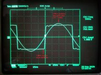
The third picture shows the oscilloscope snapshot of the waveforms.
The square wave output of the XO as is, and the sine wave obtained from the same XO filtered by a 7.5MHz low pass filter.
This means that the Timepod will measure the original XO square wave against the same square wave converted into a perfect sine wave.
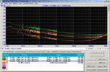
Finally the fourth picture shows phase noise and jitter comparison between the 5 MHz square wave XO with (pink line) and without (blues line) the low pass input filter.
As you see the two plots are exactly superimposed and the measured jitter is exactly the same, the harmonics of the square wave don't affect phase noise and jitter measurements in the least.
Measuring a 5 MHz square wave its harmonics fall into the passband of the input filter used in the Timepod (27MHz) but phase noise and jitter results are exactly the same, which demonstrates the reliability of the gear even with square wave clock.
So, please stop telling your own story when the reality is the opposite.
Andrea
I hate to repeat myself, but since your assumptions are far from the reality I have to do it.
We have already demonstrated that the Timepod measures correctly square wave oscillators, let me recall here.
We have measured the phase noise of a 5 MHz CMOS output CTS oscillator with and without a low pass filter with 7.5 MHz corner frequency before the input of the Timepod to suppress the harmonics above its fundamental.
The first picture shows the spectrum analysis of the square wave at 5 MHz without the input filter (green curve) vs the same square wave with the filter at 7.5 MHz (blue line).
As you can see the spectrum of the signal without the low pass filter is charged with lot of harmonics, while inserting the low pass filter the harmonics practically disappear.
This means that the first 4 harmonics (10MHz, 15MHz, 20MHz and 25MHz), which have the higher energy, are not attenuated by the Timepod LPF at 27MHz.
They are captured by the ADCs exactly as are, so there is no conversion into sine wave.
The second picture shows the AC characteristic of the filter we have used.
The third picture shows the oscilloscope snapshot of the waveforms.
The square wave output of the XO as is, and the sine wave obtained from the same XO filtered by a 7.5MHz low pass filter.
This means that the Timepod will measure the original XO square wave against the same square wave converted into a perfect sine wave.
Finally the fourth picture shows phase noise and jitter comparison between the 5 MHz square wave XO with (pink line) and without (blues line) the low pass input filter.
As you see the two plots are exactly superimposed and the measured jitter is exactly the same, the harmonics of the square wave don't affect phase noise and jitter measurements in the least.
Measuring a 5 MHz square wave its harmonics fall into the passband of the input filter used in the Timepod (27MHz) but phase noise and jitter results are exactly the same, which demonstrates the reliability of the gear even with square wave clock.
So, please stop telling your own story when the reality is the opposite.
Andrea
Attachments
@Andrea @Ian
Guys you are both great engineers and I don't see the need to keep this ping pong going.
Can I suggest that Ian creates his new sine to square solution and we see what his outputs are.")
At the end of the day this is a hobby and we all care about getting the best sound for our hard earned money and having fun with great music.
You both design FANTASTIC stuff and lets enjoy all of that
Guys you are both great engineers and I don't see the need to keep this ping pong going.
Can I suggest that Ian creates his new sine to square solution and we see what his outputs are.
At the end of the day this is a hobby and we all care about getting the best sound for our hard earned money and having fun with great music.
You both design FANTASTIC stuff and lets enjoy all of that
So distorting reality is constructive criticism?
My last post is a repetition of what I have already explained and demonstrated time ago
The Well Tempered Master Clock - Building a low phase noise/jitter crystal oscillator
It was clear at that time, but now the question was raised again without adding anything to what had already been said.
"The results tend to have better close-in phase noise and worse phase noise floor than it should be."
That's not true, based on the tests we have carried out (post #6727) and on third party measurements (post #6721).
So the only constructive criticism would be demonstrate the opposite rather than merely claim the opposite.
Moreover we have also designed another sine to square converter using a modern and expensive device like the LT6957, but the measured results was almost the same.
BTW, I have said we are happy to try a better sine to square converter, and then we look forward to get Ian's board.
This ongoing debate, has IMHO produced some constructive advancement. Andrea's early criticism of FIFOPi suggested that LRCK signal was being passed by FIFOPi with less fidelity than MCLK. He maintained he had a product in development that would be superior. Ian responded by launching Reclockpi. As a user of WTMC, FIFOPi and Reclockpi, I found this to produce music that in my ear sounded more pleasing. It allowed me to get this benefit without scrapping everything I had built around FIFOPi to try Andrea's version.
Now Ian is questioning if the squarer that feeds FIFOPi is limiting performance. Sound like he intends to build an alternative. If it moves the bar forward we all can benefit. While the measurement debate seems to be going nowhere in practice I think the only way to settle the question of whether the shape of the square wave matters will be to produce one and let people judge whether it produces sound that is different and if it is more pleasing.
I listen to Nelson Pass discuss his design process. Of course it all starts with theory and measurements, but at some point he builds some prototypes. A group of trusted listeners decide which one will sound the most pleasing to the biggest market, and then the product gets launched.
@wlowes
this is true, I have never argued about listening impressions, and I'll be happy to try a different sine to square converter compared to the existing ones (STS with the AC04 and FSDO with the LT6957).
The measurements are another thing because they involve data wich are easy to compare without doubts.
At the end an alternative sine to square converter can be compared with listening impressions, while measuring it is a little difficult.
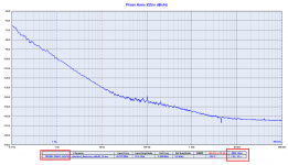
Since Ian said he trust the Timepod when measuring sine wave oscillator, please take a look at the plot of the DRIXO at 22.5792 MHz.
It's a sine wave oscillator so Timepod measurement is reliable: the measured RMS jitter is 76fs.
I assume Ian will design the perfect sine to square converter so the jitter is not degraded during the conversion.
Therefore the jitter at the output of the sine to square converter will be exactly the same of the sine wave oscillator.
Then, how one thinks to measure a jitter of 76fs since the Lecroy digital oscilloscope has a jitter floor greater than 2ps?
Sorry but it's not possible without a different and suitable tool.
this is true, I have never argued about listening impressions, and I'll be happy to try a different sine to square converter compared to the existing ones (STS with the AC04 and FSDO with the LT6957).
The measurements are another thing because they involve data wich are easy to compare without doubts.
At the end an alternative sine to square converter can be compared with listening impressions, while measuring it is a little difficult.
Since Ian said he trust the Timepod when measuring sine wave oscillator, please take a look at the plot of the DRIXO at 22.5792 MHz.
It's a sine wave oscillator so Timepod measurement is reliable: the measured RMS jitter is 76fs.
I assume Ian will design the perfect sine to square converter so the jitter is not degraded during the conversion.
Therefore the jitter at the output of the sine to square converter will be exactly the same of the sine wave oscillator.
Then, how one thinks to measure a jitter of 76fs since the Lecroy digital oscilloscope has a jitter floor greater than 2ps?
Sorry but it's not possible without a different and suitable tool.
Attachments
...sure, isolatorPi then fifopi then reclockpi.... is A LOT OF money ...then optional better regs which could have been integrated still the beginning, etc... . Clearly made as cars marketing.
I'm beginning to ask myself if all of this is not a good contributor to pollution, firstly... improving return to garbadge. DIY wastes !
...then optional better regs which could have been integrated still the beginning, etc... . Clearly made as cars marketing.I'm beginning to ask myself if all of this is not a good contributor to pollution, firstly... improving return to garbadge. DIY wastes !
right you are diyiggy. A lot of $ and space But I think it is useful to have this lego set option where you can choose how far you go. Certainly if every consumer has its own lithium/supercap power supply it will be big complicated and expensive. But still a fraction the cost if you went out and bought something that attempted this as a commercial product.
Restraint is difficult. For me I limited myself to one clock, linear power supplies (of my own design) stayed off the supercap path. I tried supercaps and fully realize their potential to influence sound. I have an old stash of BG caps that to my ear serve a similar purpose. So I'm using a lot of old recycled stuff that costs me nothing. Not the ultimate but good enough for me. But to those who choose to go all out, my guess is they are pleased with the result.
But I think it is useful to have this lego set option where you can choose how far you go. Certainly if every consumer has its own lithium/supercap power supply it will be big complicated and expensive. But still a fraction the cost if you went out and bought something that attempted this as a commercial product.Restraint is difficult. For me I limited myself to one clock, linear power supplies (of my own design) stayed off the supercap path. I tried supercaps and fully realize their potential to influence sound. I have an old stash of BG caps that to my ear serve a similar purpose. So I'm using a lot of old recycled stuff that costs me nothing. Not the ultimate but good enough for me. But to those who choose to go all out, my guess is they are pleased with the result.
oh I forgett the I2StoPCM that is not exactly simultaneous mode proof for the TDA1541 chip as written here at DIYAUDIO and said to me by one of the best trusted TDA1541A DACs designer that is not on this site but has his own brand...
Oh I forgett the optional isolator of the first fifo board which could have been in the same board and not a stacked expensive option, etc ! and the master clock that is not functioning without the logic of the previous fifo board but still on a different pcb to split the fronting price of each pcb to make a feeling of less expensive while all boards are mandatory and split parts of a whole same design.
OK it has the merit to exist and it's fine as a worldwide premiere for diyers. But it's also marketing and clearly a little business too. It's ok as long as the customer diyer see it. But a lego car is never as good as a true standalone made car.
So the ping pong is not exactly equal and unpartial : one is defending his brand and incomes, the other player not being commercial involved at the moment is defending a design.
I'm not far with all of what I spent since the beginning of these front end improvement of the cheaper on shelf Total DAC (5000 euros?). Well i assume it's a hobby too and a hobby can be expensive, the inal result is not always the goal, the involved pleasure time is and it can not be priced too if I stay fair enough.
I just regrett to spend so much monney to listen to there is a bug in the design each time or almost each time.
The good news is I am going to spend more for my complex tda1541 DAC to benchmark best opa chips with discrete diamonds and also a third tubed 6NP23 and a further E88CC... then I will finish without monney, loose my flat and finish in the street with an old Sony Walkman with orange buds on the head sleeping in front of Hifi shops, while young will hurt me saying I have polluted their world and future, lol !
Last edited:
Hi All,
Just wanted to check in on a couple of things:
1) Has anyone compared the SPDIF out on the Transportpi compared to say the Pi2aes? I am looking for a secondary system and want to use a reclocked SPDIF (either RCA or BNC) but didnt know which was the best hat to get for that purpose (I have the FIFOpi).
2) Would a reclocked SPDIF be a better SQ option compared to the USB output of the Rpi4?
3) If I got a USBridge, would there be any detriment to using a GPIO extender ribbon to the left side of the Stationpi (with the FIFOpi on the right)?
Thanks!
Pi2aes would be hard to beat. Just bought a audiolab cdm transport, mid 90s vintage, sounds exactly the same as ssd laptop and rpi via USB into a gustard a18. I like my Ian stack rpi, ssd, fifopi, crystek clock, batteries, dual ess q2 board and Bishkek traffos it's a fun project, but different, not better.
Just build it for fun, stop chasing rainbows guys. Next months flavour of the month will be better, again and again.
Just build it for fun, stop chasing rainbows guys. Next months flavour of the month will be better, again and again.
Hello,
This is audio but it is still business.
Before your new circuit board has passed customs the next circuit board is already on the screen on the other side.
Why cant they do it like Doede get a new update every 2 or 3 years and when there is nothing to upgrade write a blog about possible upgrades outside the " main circuit "
Maybe just always skip one update because you wont be able to sell the one you just replaced. The only things you can use again are the stand off . Not really a good example of sustainability.
I think Doede's boards once you take care of not heating up anything close to maximum rating can easily have a lifespan of twenty years.
Of course if you buy a product that will get 10 upgrades in twenty years you wont use that lifespan. Dont tell me it is an ongoing process of constant improvement. With the Dddac boards there were two major modifications that were initiated by owners with the help of Doede but it took rather long time to have them integrated into the boards. He took his time but it was worth the wait.
Greetings,Eduard
@Andrea @Ian
Guys you are both great engineers and I don't see the need to keep this ping pong going.
Can I suggest that Ian creates his new sine to square solution and we see what his outputs are.
At the end of the day this is a hobby and we all care about getting the best sound for our hard earned money and having fun with great music.
You both design FANTASTIC stuff and lets enjoy all of that
+1
- Home
- Source & Line
- Digital Line Level
- Asynchronous I2S FIFO project, an ultimate weapon to fight the jitter